Chapter 4: Prep for Surgery
OK, so we want to preserve the teal, and we’ll keep the interior decision for later.
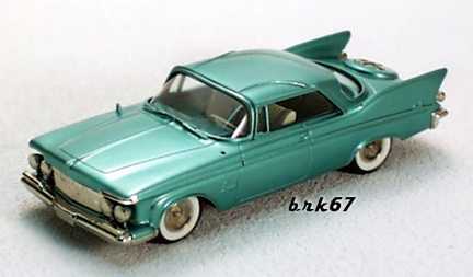
Here’s a weird teaser: a 1/47 model in teal & white on sale at http://www.automobilia.com!
NOT that the steering wheel would really be white or the dash teal!
But then, I don’t have a 2-door either. Is that a tricky color, or what?
Here’s the rough Order of Business 9we all know it WON’T go according to plan:
But first:
The car is parked outside in the secure yard behind Hurley’s Garage, where the paintwork will occur. It seemed logical to strip the trim there. It’s not too far from home, but I won’t need to move the naked body. I know this will take weeks, so I have to have a system for keeping track of all the little bits and fasteners that will come off. I figure the larger parts will be mostly self-evident. I decide on freezer bag with lockstrip tops and labels. I’ll put all the little parts in bags with labels on them, grouped according to the larger pieces where they belong.
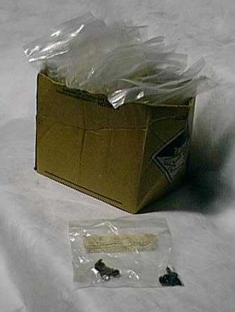
Sandwich Bags To the Rescue! One for the fasteners and tiny bits of each trim piece or set that comes off.
I’ll also need to keep a kind of journal to help remember the order of disassembly and assembly and any special notes. I’ll use a little notebook and this webpage. The notebook will go ‘in the field’ and the discipline of writing this site will make me expand the cryptic scrawl into something you (and me, after my memory fades) can use.
I decide to begin at the front.
The front bumper comes off easily. A few large bolts, not too rusty. Then it’s the wheel arch SS trim, also easy-out philips screws (thank goodness for cordless screwguns!). Then I get ambitious and take on the bright corner shields between the bumper and front wheel wells. The first sign of rust and recalcitrance in threaded fasteners. Soak with WD-40 and move on for now.
The rear door inner panels are off, so I decide to try the spears there. Piece of cake! The tinnerman nuts (pressed sheetmetal spin-ons) are clean and every one is reachable with a 3/8 combination wrench through the openwork of the inner door frame. The spears are off in minutes! I’m motivated to pull thee front door inners and get those spears, too. I pop the spring clips around the edges of the panel, using my now-trusty putty knife. How the devil does the inside latch handle come free? Ahh, that’s it! Remove the screws that hold in the shrome trim around it, then lift that gently up to expose another screw that releases the post clamp. Then the handle slides free of the door, still trapped in the inner panel. The panel lifts up to disengage the window sill. Before pulling it off, there are pin connectors on the back for the power windows and locks. They wiggle off OK, I take pains to make a picture on the door fasteners bag, showing the orientation and wire colors on the connectors. Spear access and removal is by very accessible tinnermans . The spears are off in no time.
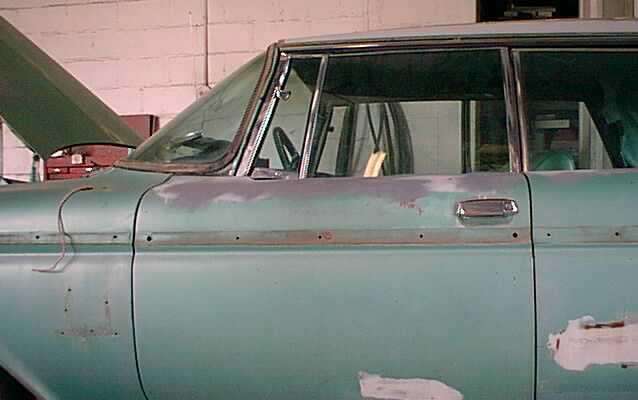
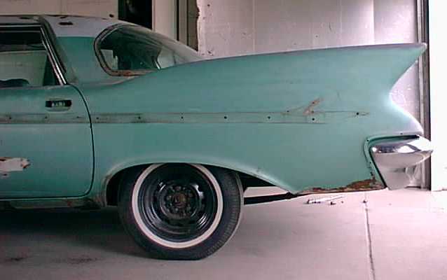
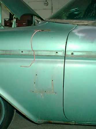
Can you see the reddish dot midway along the spear shadow on the door? It’s just to the right of the 3rd hole. There was a little (3/4 inch diameter) blob of soft stuff there and on each door in about the same place. I presume it’s anti-rattle compound to damp the shock of slamming doors. Must remember to put some in when I reassemble. Also note the large end holes on the door spear shadow. The ends were held with real threaded studs and special machine nuts and washers. I guess it worked, they were still in place forty years later.
This is too easy. Move to the rear fender spears. Let’s see: the nuts in the trunk are easy enough. The one nearest the door jamb requires removing the rear window inside chrome trim (more easy-out philips screws), plus tearing away some of the headliner (shot anyway) to get at it. Even so, it turns out to require reaching through a hole through two metal walls, both offset from each other and from the nut (so I can’t get there with even a swivelled socket). Whatever I use, if I drop it in there, it’s gone: a rattler forever. Solution: tie a couple feet of clothesline to the 3/8 combo, through the box end. If I put the wrench in the hole first, I can just get my left hand through and get the wrench to the nut. Ouch! Those punched sheet metal edges are SHARP! First blood drawn. Fortunately, tinnermans don’t take or hold much torque, so I can two-finger them off and I don’t drop them. Success!
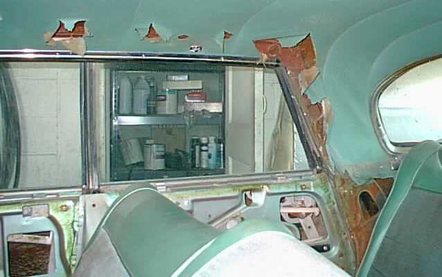
See that Little Dark Hole in the Body, Next to the Rear Seat? The Nut’s deep in there, past another hole in a second layer of inner steel!
But wait, there are still two fasteners over the wheel well. They can’t be reached from the trunk or from the rear seat area. Stumped. Appeal to the IML and several of the cohort assure me that those are just push-in fasteners (and the same are used on the fender scripts, which are similarly inaccessible from behind). All I have to do is GENTLY pry off the spears (and scripts). RIIIGHT! NOO PROBLEM. Also No Choice. I get a putty knife and some wooden shim wedges and begin inserting and tapping. Sure enough, it works! They all come off with no loss. There are little spring clips left in the holes that caught the pot metal posts (now pried away). These have little barbs behind the sheet metal, too, to hold them in. To get them out, I grind a tiny electronics screwdriver tip to fit under the outer flange, pushing in one side enough to get the barbs up and out. Then the same on the other side , while leaving a wedge on the first. Sometimes they need a little tug with needlenoses, but all come out with negligible damage. Into the sandwich bags!
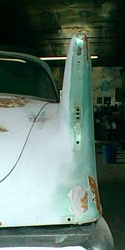
Rear Fender, showing Spear shadow & Mounting Holes. The back 4 all had rubber washers. Why not ALL of them?
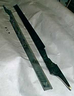
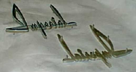
Rear Spears and Fender Scripts Removed. Notice the unthreaded cast posts for insertion through holes in Body. The 6 script posts and 2 middle posts of spears press into spring clips in body holes. All others use tinnermans.
Next goes the grille. Another easy removal once I locate all 20 nuts holding it in. These are real machine nuts, engaging threaded steel studs.
The front spears prove more difficult. They use the plain stud & tinnerman method, but they’ve caught all the years’ road splaqsh, so many of the posts are just nubs. Enough to be holding, but when I touch the nuts, the pot dissolves and the nut falls free. Make a note, We’ll need to figure away to reattach these. There are two interesting twists. The trailing edge is held on with a real threaded nut and stud. It’s a little awkward to reach. The front door has to be open halfway (not more, not less). The other artifact is the riser clips that are present on some of the tinnerman studs. They look original, and raise the engagement point for the nuts on the posts. These nuts lie VERY close to a standing seam in the sheetmetal, making it hard to seat the nut flat. I wonder if these clips were used to get a local flat surface where needed? Maybe they just give a second chance if the nuts stripped the root of the post? I note on the bag labels which posts had these lifter clips.
I return to the lower front quarter shields. This time they yield to some gentle seesawing of the nuts to loosen the scale. They drop away. Now for those eyebrows and lights. HAHAHAHAHAHAHAHA!!!!!
There is a metal inner fender plate spanning between the engine bay wall and the outer fender, ahead of the wheel well. It blocks all access to the forward prow. I try reaching up ahead of it. No Way, unless I break my arm in 3 new places. The plates will need to come out. Four bolts each, big and not too rusty. They work out. On the passenger side, the plate comes out with a tricky but do-able 1-1/2 twist and a backbend. I can see into the flying brow. On the driver’s side, it’s not so simple. There is a vacuum canister up there, bolted to the plate I want to remove. Those bolts are frozen. Even with the plate disconnected, the three-dimensional assembly with the vacuum can prevents the 1-1/2 gainer with a twist that worked to get out the passenger side piece. Time for a cool drink. No pictures of this it’s just too dark up under there.
After sizing up the situation, I conclude that if I jack up that corner and turn the wheels slightly to the left, and turn the connection of the vacuum hose, I ought to be able to get this out. I’m very glad it’s not too heavy. It almost works. In the end I have to pull out on the fender a bit (all elastically) and flex the plate a little to squeak by. I look like I’m wrestling with the car: both feet, both hands, and a shoulder are engaged and actively participating, but it comes out. The eyebrow chrome is provided with the real threaded studs and the nuts are clean.
Why did Chrysler use some threaded and some tinnermans (and some push-ins?) – so far I’ve been through at least half a dozen different fastener types, all doing basically the same job. Were the parts designed by different people who never spoke with each other?
Access to one of the eyebrow nuts is through a notch in the underlying signal lamp housing (mind you, this is all up in the deep dark cave of that fender brow). Look closely at the lamp picture below to see the notch at the top. They must have put these in with rubber wrenches, because the nuts do NOT align with the notches. A little more elastica pressure, this time on the housings to get a socket over the lower edge of the nuts. I tried to take out the lamp first, but it can’t be the eyebrow trim lays over it. In fact, there are four philips screws holding each lamp from the outside, two are visible below the lens, two are covered by the eyebrow. Anyway, they’re out. The headlights come quickly, too.
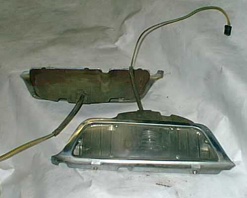
Parking Light Assemblies: Note notch at top of upper one: that where that last Eyebrow-holding nut is hiding – almost aligned!
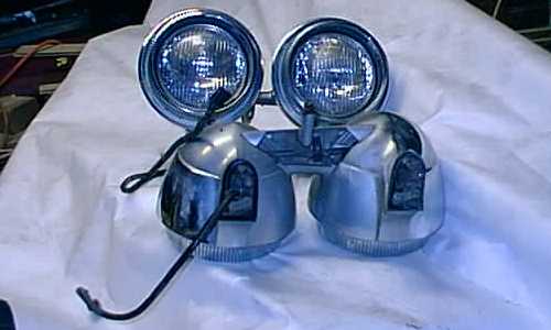
More than 20 pounds per set, the headlight pods are an easy 5-bolt removal
So, you’d figure the taillights should be the same, right. Well, not exactly. Of course the access is limited as it’s necessary to reach up into the fins to get to the mounts, but – that’s the price of Beauty. There is a single tinnerman holding the little chrome detail below each lamp and the lamps are each held with two real studs and nuts. They come out together (the studs and nuts, that is. They’re joined by oxide more firmly than the studs to the lamp housings. Oh well, Into the ‘taillights’ bag. Here comes the trick: The connectors on the pigtail wire (which is soldered directly to the lamp contacts) are TOO BIG TO FIT THROUGH THE HOLE IN THE BODYWORK! Incredible. Thes must have been put on AFTER the lamps were assembled to the car! Question to IML again. Some say cut. Some say file out the hole. Hmmm… I try that electronics screwdriver again. With some jimmying, I pop the plastic cover off the actual brass connectors. Will they fit? YES (though only one at a time). I think these lamps are fine art in their own right:
Taillight with black connector covers removed and with secondary chrome and its tinnerman. I have two spares of these. I believe I’ll display them. Note the TINY little holes on the fin metal (3 together) that are the mounting and pass-thru for the wires. The rascals!
The roof spears came off easy enough. I poked through the headliner as needed to access the tinnermans. A mystery was solved at this point, too. I had been wondering why this car was so clean and rust-free outside, but the inside showed copious evidence of long-term wetness. The rugs are rotty, the floor metal has a light red surface rust. When I pulled the back seat to access the fender spear nuts, I found every edge and joint there with that same reddish surface rust that screams WATER on steel. Even the rearview mirror and the chrome over glass was rusted! When I removed the roof spears, the passenger side piece was properly sealed with gummy stuff at every hole. The driver’s side, though, showed no sign of EVR having had any sealant at any hole! America’s Most Carefully- Built Car – INDEED! I suspect that this car has had a subtle leak through those hole for all its life. Maybe never enough to show as rain inside, but enough to promote the toprust?
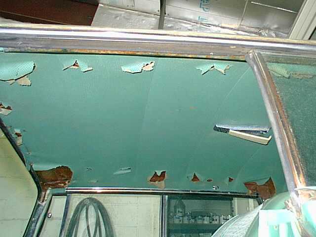
Headliner Punched out for Access to Roof Spears and Windshield Header Trim. NO! You cannot have my Dome Light Lens!
Pulling the drip rail moldings required a putty knife, ground short to increase pry leverage. I worked along the lower edge of the molding, springing it up by prying against the inner molding (that carries the rubber seals). A Piece of cardboard under the pry prevents scratching that inner molding.
The window moldings are ALMOST standard. Mostly they are held on with the ordinary spring clips that were universal in those days. These are easily popped with the proper tool, a kind of hooked knife. This is one of those practice things- way easier to do the second time than to describe the first. The variance is in the windshield header. This is a three part assembly that is screwed on from the inside (tinnermans on real studs this time). To get at the nuts (there are 7 altogether), you need to remove the inside rearview mirror and the screwed-in chrome (or in my case, rusted) reveal moldings above the windshield inside. Then you can peel back the front edge of the headliner to find the access holes to the nuts. I just poked into the holes right through the old headliner. I could find them by feel. Here is the outside windshield header removed. You can see the central part has its own stud. These are SS parts, not pot chrome, so there are clips that hold the studs. Into the bags they go!
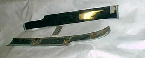
SS Windshield Headband Assembly. They all come off together.
At the back window, there are again mostly standard molding clips, but there are also four from-the-inside fasteners, located where the riser moldings on either side meet the top and bottom edge moldings. I didn’t realize this until too late, and by applying some of that magic elastic stretching, I was lucky enough to get the moldings of undamaged. But those four clips have studs and nuts accessible from under the inner chrome reveals. It would be impossible to put the moldings back ON without removing these.
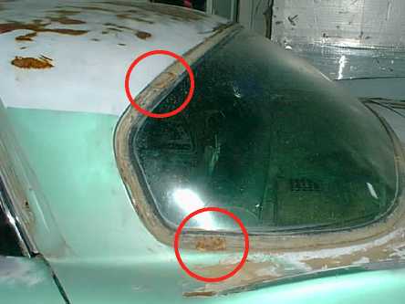
Whoops! There are two Joiner Clips there!
Last at the front, I removed the cowl grille, mirrors, and wipers. The cowl grille has two visible screws, one at either end, but a third one is hidden beneath a push-in/pry-out pot part that covers the central inch or so. Again, a gentle working up is required.
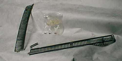
Cowl Vent Grille: note small center piece & 3 crews in marked bag.
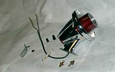
The right side mirror was trivial. To get out the remote-control driver’s mirror, I loosened the dash retainer ring and taped a cord to the control knob. After removing the mounting screws outside, I worked the control knob with its cord up through the firewall and fender mounting holes. I left the cord in place to ease the return trip. I think it would be OK to omit the cord here, but it can’t hurt!
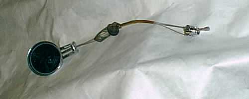
Remote Control Mirror Assembly
The Cord for the Mirror. You can also see the Holes for the Script & Spears.
Here’s the toothless hammerhead, mostly stripped:
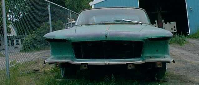
Front Stripped: Truly Fierce.
Oh yes, that back bumper. I couldn’t see how it went on unless the body were added later. After my chinese puzzle experience with the front fenders, I believed it coulda happened! The troupers at the IML came through, though. Carmine clued me to hidden plugs under the trunk carpet that give access to the secret screws. I couldn’t get out the lower bolts anyway, though, so I left the bumper on for now.
That SS reveal along the lower front also can’t come off. It’s held on with miniature stovebolts, long since rusted to their nuts far more strongly than the squares under the heads in sheet metal. Those will need to be cut off.
The last challenge was the SS rocker moldings. At first I couldn’t see how to remove them. HELP, IML! Several experienced restorers suggested that the molding clips are to fragile: leave the moldings and paint to them. Others argued to remove them (you only go ‘round once in life. Ya gotta grab for all the gusto you can). I decided to go for it and found the grips at the lower edge. They looked like the same catches as used on window moldings, so I used a putty knife under the lower edge and bing-bin-bing, every clip released. The moldings then lift upward, sort of sliding along the body contour to release their turned-down upper lips from engagement with the free top edges of the clips. This is harder to explain than it is to do, so since it generated so much controversy on the IML, I have illustrated it here:
Rocker Clip (screwed two places to body). There are six on each rocker.
Here is the removed rocker with the actual clips:
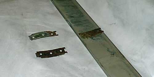
Underside of SS rocker trim, with spare clips. Lower edge of molding (as installed) shown here to right of image.
I think that’s it. I f I haven’t lost your attention yet, take a look at a nearly naked Imperial below, then jump to the Bonus Images page and see where this project (and I) live, a view of the engine bay as-received, and a view of the undercarriage (it looks BRAND NEW!).
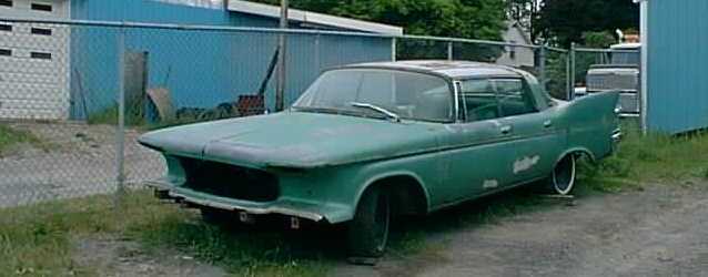
Take Me to Your Paint Shop! (Yes, that wiper was stuck – it’s off now)
Next Chapter Prior Chapter FrontPage & Index Bonus Images Page