|
AUTO-PILOT
The auto-pilot is a driver operated speed control. It can be used two ways:
- As a speed indicator when pre-set speed has been reached.
- As an automatic vehicle speed regulator.
Adjustments and tests must be made in proper sequence as follows:
- Accelerator linkage adjustment.
- Control cable adjustment.
- Electrical tests.
- Road Tests.
ACCELERATOR LINKAGE ADJUSTMENT
(figure 1)
- Automatic choke off and throttle at curb idle.
- Tool C-3844 over pin and in notch.
- Adjust link at lock-nut.
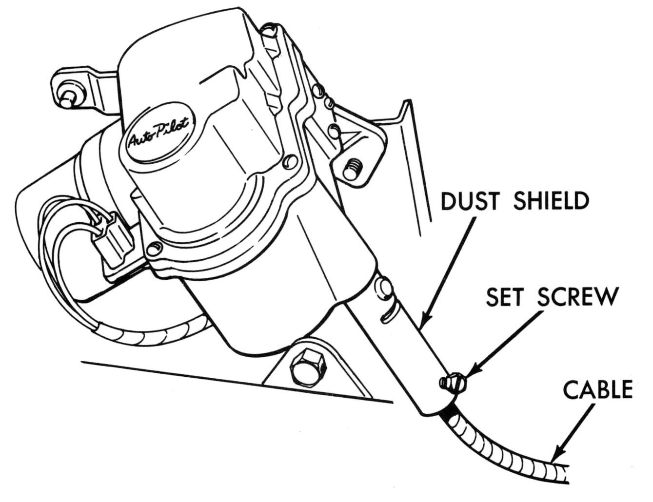
CONTROL CABLE ADJUSTMENT
(figure 2)
- Loosen set screw in cable dust shield.
- Instrument panel control dial C.C.W. to stop.
- Push control cable into dust shield lightly to stop.
CAUTION: Do not force.
- Make sure control dial is C.C.W. to stop and tighten dust shield set screw.
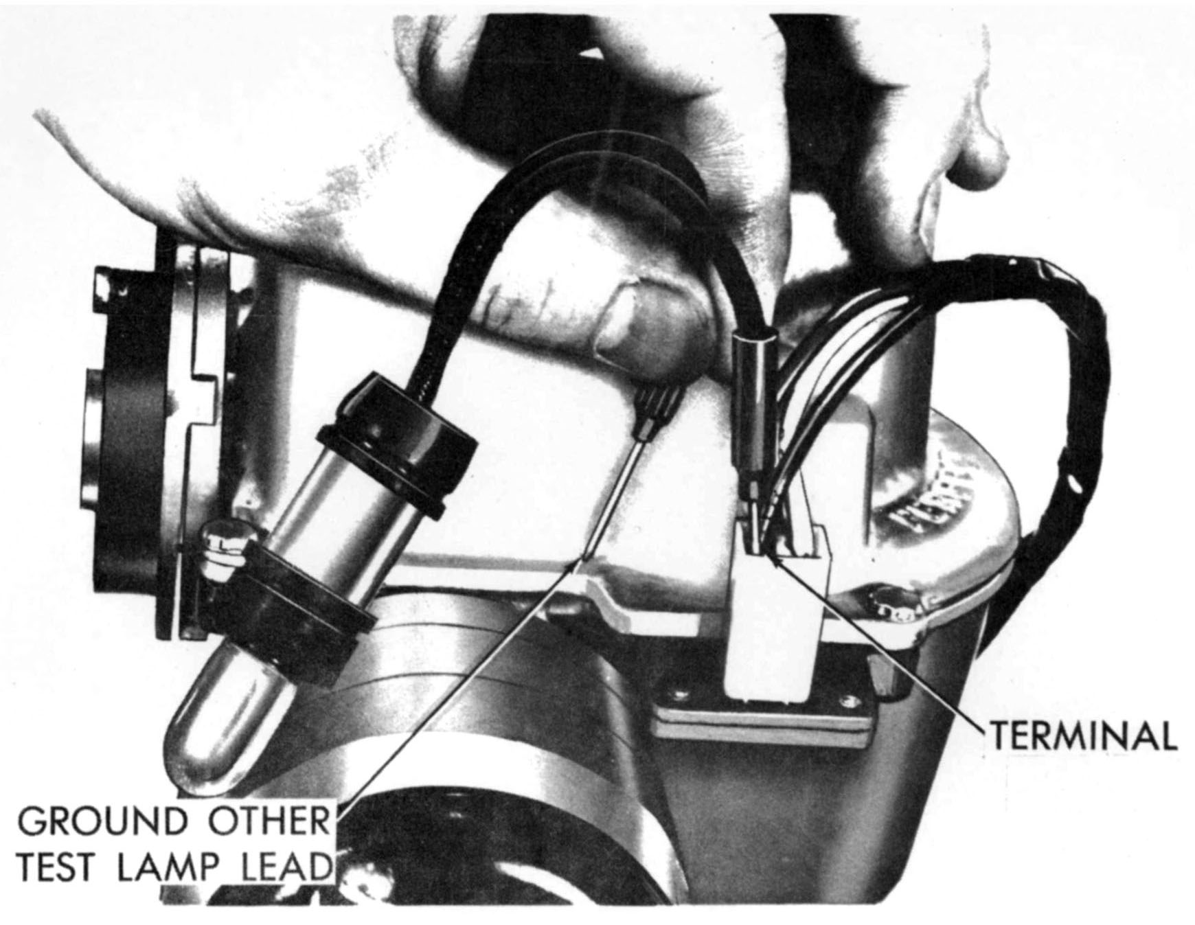
ELECTRICAL TESTS
(figures 3-5)
- Ignition switch on (engine not running) and control button out.
- Test made with 12 volt test lamp at auto-pilot multi connector.
- At red wire to ground - Lamp should light. If it does not light, check for open between auto-pilot and ignition circuit through bulkhead. (Figure 3)
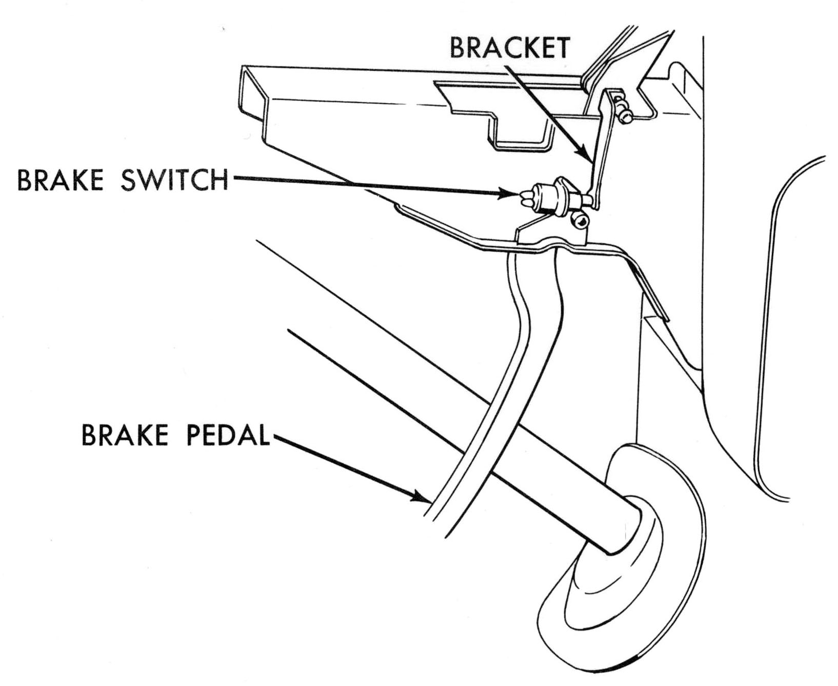
- At blue wire to ground - Lamp should light. If it does not light, check for open between auto-pilot and ignition circuit through bulkhead connector and brake switch. (Fig. 3)
Light should go out with 1/4" to 1/2" of brake pedal movement. (Figure 4)
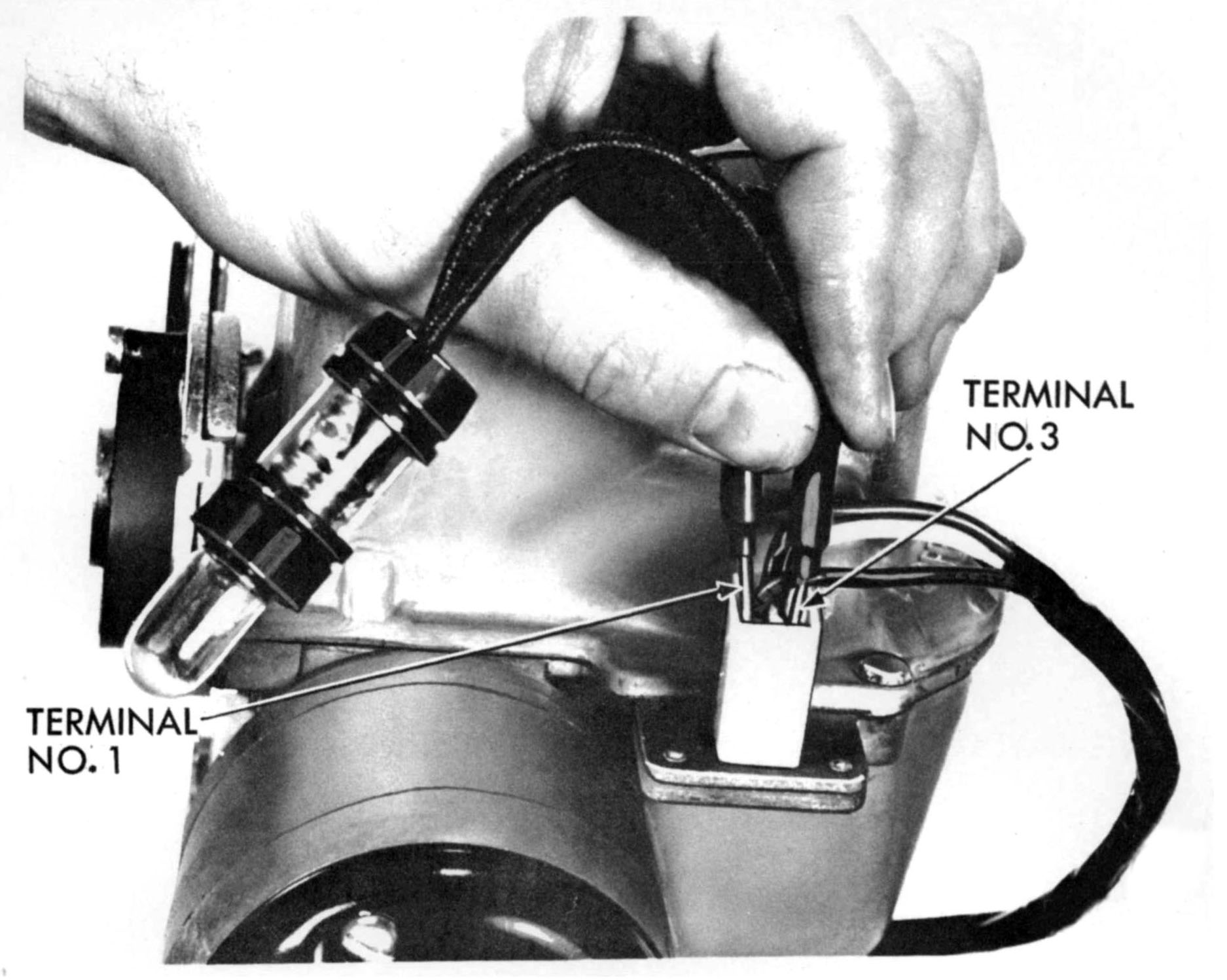
- Red wire to black wire - Lamp should light. If it does not light, check black wire for open between auto-pilot and panel control through bulkhead. If circuit complete, check control for proper ground. (Figure 5)
ROAD TEST
- Drive on level road. Control set CC.W. to stop.
- Engage auto-pilot. Minimum speed setting should be 22 to 30 M.P.H.
- If not within specifications, adjust low speed setting.
|
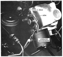
figure 1.
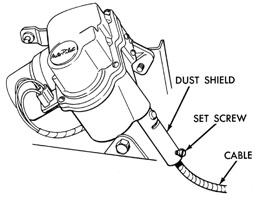
figure 2.

figure 3.

figure 4.
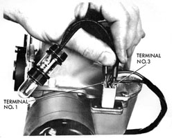
figure 5.
figure 6.
|
|
RADIO
- ITEMS AVAILABLE AS RADIO ACCESSORIES FOR DODGE CARS.
- A.M. Radios - All Transistor
- Economy Line - 2 1/2 watt power output available all cars except 880.
- Delux Radios - 5 1/2 watt power output available all cars except Dart.
- F.M. - A.M. Radios - All Transistor
- 5 1/2 watts power output available all cars except Dart.
- Reverberators - For concert hall sound available in all cars except Dart and Suburban Models. Released as a MoPar package for all cars except suburban and convertible.
- Rear-seat speakers, antennas front mount, rear mount, and power.
- DISCUSSION OF EXPECTED OPERATIONAL PERFORMANCE OF A.M. RADIOS
-
A.M. radio will provide acceptable performance throughout the country in general.
However, as always, there are exceptions and these exceptions became important where we are trying to understand a customer complaint.
- When a car is traveling in an area where there is a high density of metal, such as mountainous areas, tunnels, bridges, etc., there will be a fade out and even occasional loss of radio signals.
Where a number of stations from several locations assigned to the same frequencies are received at the antenna, these will notably interfere. This condition causes the listener to think the radio has no selectivity. The condition will vary as the car changes location, and will vary from day to night in the same location. This problem is caused by the fact that a great number of new stations have been licensed by the F.C.C. in recent years. 3,268 new A.M. stations were added from 1941 - 1962.
Since radio waves in the A.M. band do bounce off the atmosphere, numerous signals from stations many hundreds of miles apart can be bounced into a given location. As the car moves through these locations, an undesired effect takes place. Chrysler radios have the best circuit designs available for minimizing this undesirable effect. However, due to the nature of A.M. radio, it cannot be entirely eliminated.
- It is important to know, too, that some of the new A.M. stations are only authorized to broadcast during daylight hours. Therefore, you could be listening to a station in the daytime and when you turn on the radio at night, the station is not there. In some cases, several stations are not there that you heard during the day.
- A.M. radios are sensitive to all electrical disturbances. These come from car and truck engines, neon signs, storms, and power lines. Noises of this kind vary with location and the A.M. radio cannot reject them.
- A.M. - F.M. RADIOS
This is a relatively new item introduced in our cars this past year. F.M. radio offers new and varied program material normally not available on A.M. stations. F.M. radios, due to the short wave length of the signal, will not fade in and out when the car goes under bridges and viaducts. In addition, it normally does not respond to noises from power lines, neon signs, etc.
However, there are some special characteristics of the F.M. radio which influence mobile receivers. Chrysler A.M.-F.M. radios perform as well, or better, than most home receivers. However, when a radio becomes mobile, it is influenced by a continually changing set of conditions at the antenna.
Therefore, the following general characteristics regarding F.M. will be of interest to you.
- Good reception can only be expected consistently when the receiving antenna is on a line of site with the transmitting antenna. The reason for this is the high frequencies of the F.M. band, 88-1O8MC are not reflected by the atmosphere.
- This line of site requirement means that the operating range of F.M. stations is limited, much like television stations. This range is approximately 35 miles.
- Buildings and hills can easily blank out the signal in fringe areas (weak signals).
- In metropolitan areas, wnere the signal strength is very strong, signals will bounce off buildings, bridges, etc., this is the exception to the line of sight requirement.
Mobile F.M. receivers, because of the fact that they can move through the strong signal areas of numerous stations, even within relatively short distances, are subject to what we call "capture effect". This occurs when the radio is tuned to a station that is some distance away, and the car passes the antenna of a station which is operating in the next channel. The F.M. radio will pick up the station being passed. This occurs because the signal strength of the station in the adjacent channel is often thousands of times stronger than the station tuned to, and causes the automatic frequency control to try to lock on the strongest station.
Our radios are designed to minimize this effect, but it does happen especially in large cities where there are a larger number of stations.
- The Eastern part of the country has the highest number of F.M. stations and they are concentrated in cities where the population is highest. However, in rural areas, stations are few and far between. Therefore, on trips, the F.M. radio may only be able to pick up one or two stations and in some locations none at all.
- When the radio is operating in a weak signal area, the noise limiting action is not as effective, and the radio will pick up ignition noise from passing vehicles.
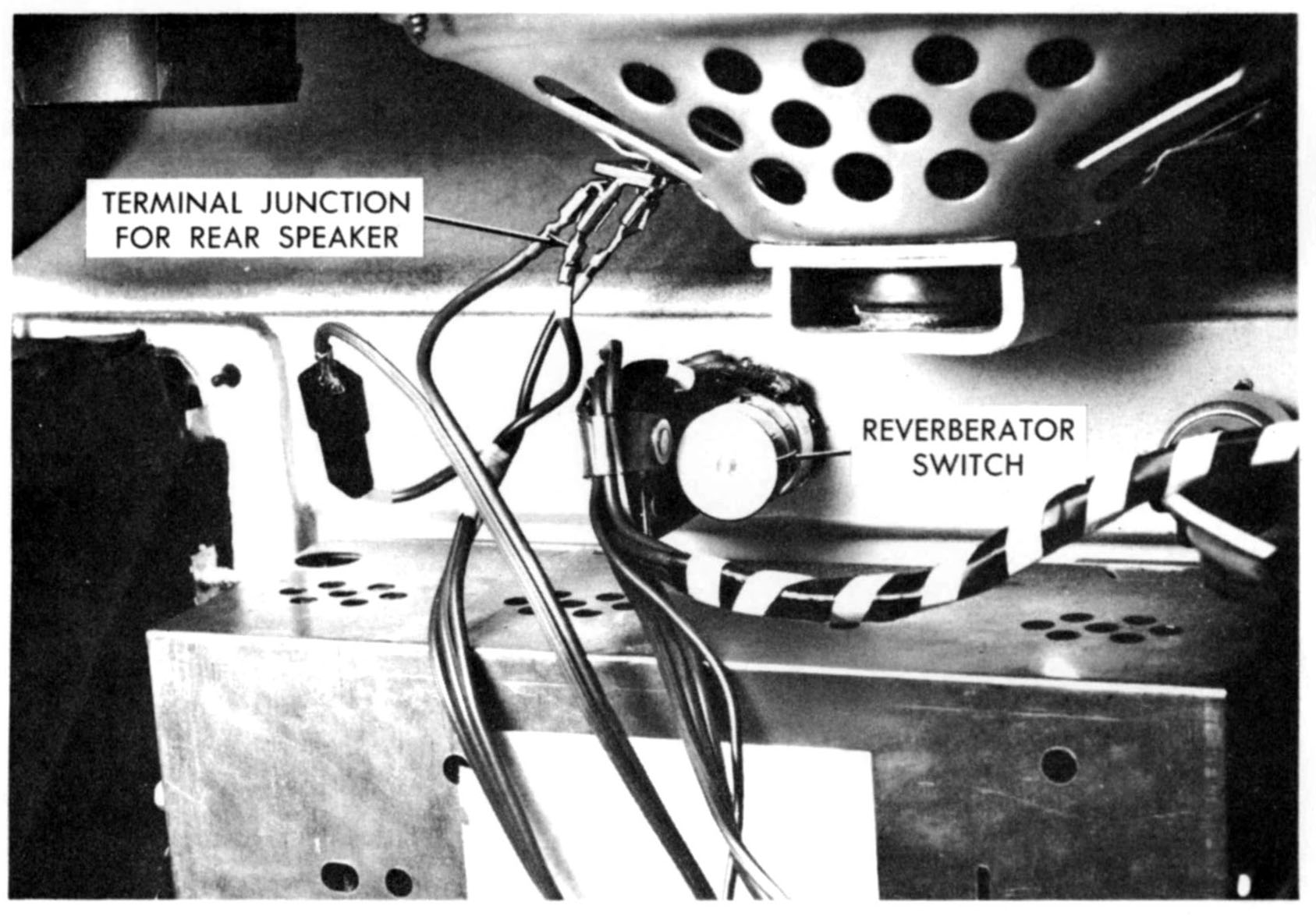
- REVERBERATORS
- The reverberator is composed of a mechanical delay line and a simple transistor amplifier. The delay line causes the signal to be reproduced in the rear speaker about 22 milliseconds later than the front. This provides an echo effect similar to that obtained in a hail and is very pleasant on music programs. Reception is not desirable on voice programs.
Chrysler reverberators are superior to all competition. We have a completely adjustable unit which provides a control over the amount of reverberation desired. The push-pull switch enables the customer to set the control where he desires, and it will remain in this position regardless of the number of times he turns it on and off.
The reverberator unit is operated separately from the radio. The speaker fader control has a push-pull, on- off switch which applies battery power to the unit. The switch should be pushed in when the radio is not in use.
When the reverberator is off and the radio is on, the rear speaker functions in the normal fashion.
- When the car is traveling on very rough or wash board roads, the delay lines in the reverberator will begin to vibrate much like a spring on a screen door when it is slammed. If the reverberator is on when this happens, a very undesirable sound is reproduced in the speaker.
- CUSTOMER COMPLAINTS
These different characteristics in the radio systems have been mentioned to help you understand the normal limitations imposed on equipment when it is placed in a moving automobile.
It is hoped that this information will help you recognize the difference between a true radio problem and the apparent problems which arise from the unusual effects of mobile radio.
This run-down on the problems encountered in mobile radio equipment is intended to point out the necessity of talking to your customer to determine the exact natUre of the complaint. If possible, it will save you much time if the problem can be demonstrated.
There is also a pamphlet placed in every car that has a factory installed F.M. - A.M. radio called "Facts About F.M. Radio Reception in Automobiles". This tells the user what to expect from his F.M. radio. You should make yourselves very familiar with this book. It will answer most questions about the problems I have touched on here.
- DIAGNOSIS
Typical complaints and how you can best determine what part of the radio system is at fault:
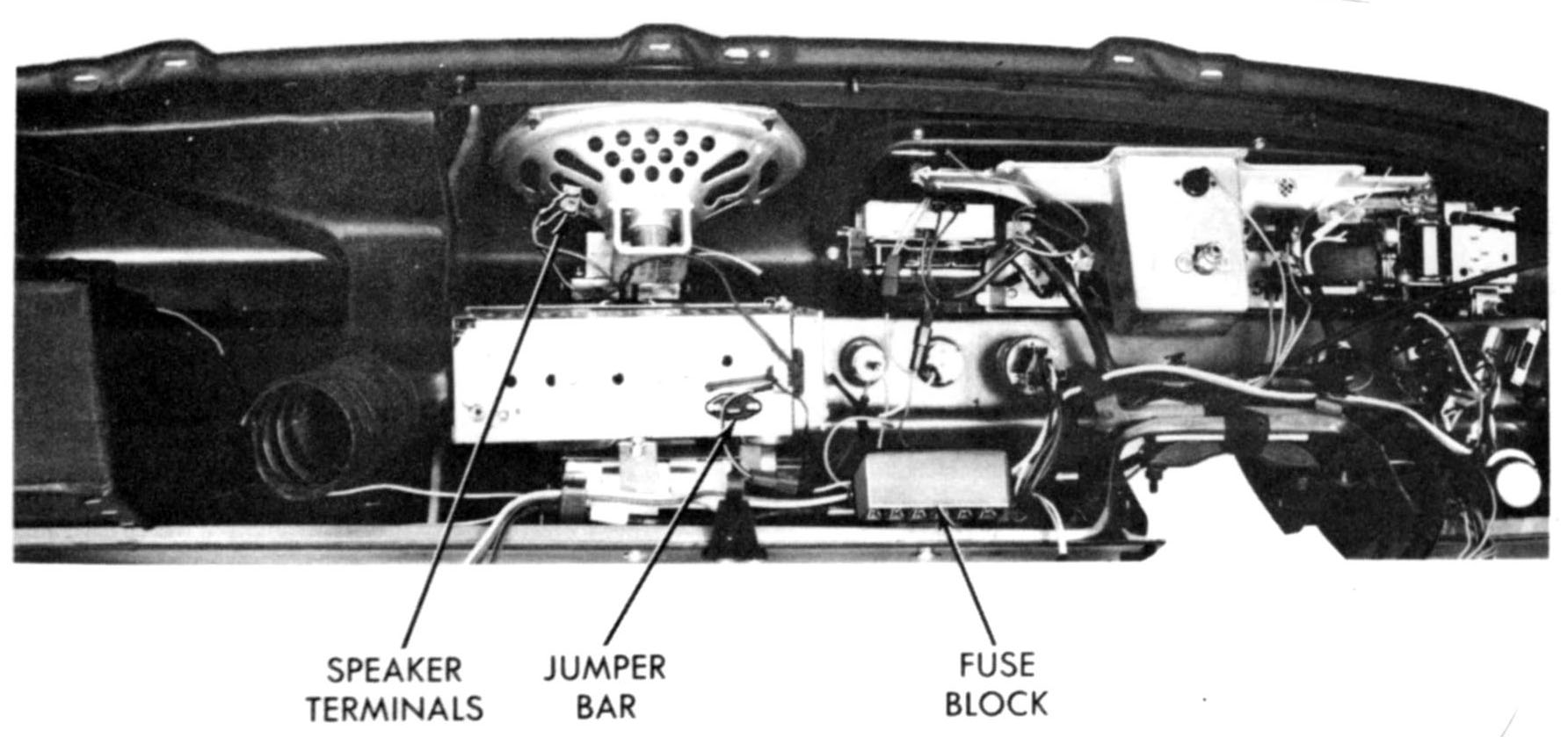
When diagnosing complaints, ascertain whether installation is correct first. If rear speaker is not used, the jumper bar must be installed at rear socket.
- The easiest, of course, is the case where the radio is "dead". There are some quick checks which you can perform before you remove any part of the system.
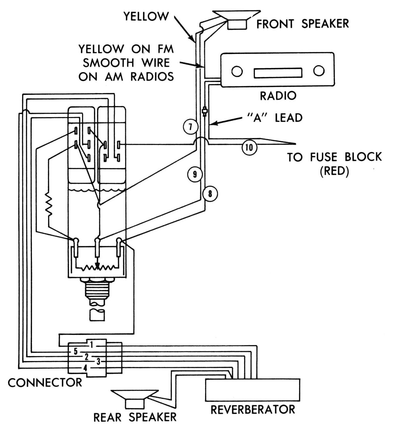
- Be sure the "A" lead (power lead) is properly connected.
- Check the fuse in the fuse box. If it is blown, merely replacing it may not be the answer. Operate radio for about 1/2 hour and be sure to run the engine.
- Check the speaker connections.
- Check the antenna connection. Be sure that it is all the way in the socket.
- Remove the antenna connector from the radio and check two things. CAUTION: Remove antenna plug by easing it out of the socket. Do not jerk on cable or the internal conductor will break.
Remove the antenna connector from the radio and check two things. CAUTION: Remove antenna plug by easing it out of the socket. Do not jerk on cable or the internal conductor will break.
Using an ohmeter or any device which will read continuity connect one terminal to the small tip of the antenna plug and the other to center extension of the antenna. This is to assure that there is no break in the lead-in wire. The other check that should be made is to connect the tester to the small tip and to large part of the plug. Here you should get no indication unless the antenna is shorted. During both of these tests move the lead-in while observing meter.
- If all checks reveal no apparent problems, then remove the radio for bench service.
- Radio has weak output.
- Perform the antenna checks.
- Adjust the antenna trimmer for maximum output. This is done by raising the antenna to a height of 30 inches and with the radio tuned to a weak station above 1400 K.C. A.M., turn the screw located near the antenna socket, carefully until maximum signal is heard. This will provide satisfactory trim for the F.M. section as well.
- If this is not the answer, it pays to check the connections to the speaker and the fuse block before removing the radio.
- Radio has crackling noise.
- When checking this condition, it is necessary to look for the conditions under which it is experienced.
- At all times.
- When engine is running.
- If it is constant (engine on or off) then it could be a faulty transistor in the radio.
- If it is only when the engine is operating, then you must check the following:
- Be sure that the resistor ignition cables are being used.
- Check the capaciter on the ignition coil.
- Be certain that all connections are tight plugs, coil, and ignition switch.
- Check antenna trim.
- Check radio mounting bracket bolts. These provide the ground for the radio chassis and they must be tight.
- Distorted Sound.
- Check speaker. For this purpose, it pays to have a good speaker in the shop with a pair of leads that fit the blade connectors on the radio. This will enable you to determine speaker problems quickly. If the distortion shows in the test speaker, the radio needs bench service. It is important here to say that you must turn off the radio while connecting and disconnecting speakers. If the radio is left on with no speaker load, the output transistor can be destroyed.
- Rear speaker has poor sound - Here again the test speaker will aid in determining the cause. Frequently, fine dust particles will filter through the grill and even the acrenolyn cloth which is now cemented to the face of the speaker causing poor sound to occur.
If the problem is vibrations or rattles, it pays to check the package shelf for spots which are vibrating when the speaker operates.
If the distortion�shows up in the test speaker, then the wiring and control will have to be checked.
 |
- Radio cuts in and out - Try to experience the condition to determine the circumstances under which it happens. Check all connections and antenna before removing radio. If the radio must be removed, be sure to indicate intermittent condition to the service station.
If you receive complaints showing problems in only F.M. or A.M. on a combination radio, it is safe to assume the problem is in the radio. All the other components are common to both sections. Include as much detail as possible about the problems in radios sent to service stations. This will help them to locate and fix the problems much faster and save the customer undue waiting time.
If complaints are encountered in the reverberator unit, it will pay to check the wiring connections, and be sure that battery voltage is available at unit. Disconnect the blade connector in the rear on the "A" lead (black wire). With the ignition switch in the accessory position, check for 12 volts with a volt meter. If you disconnect the speaker, be sure the reverberator unit is turned off.
|