
Imperial Home Page -> Literature -> Articles -> New Features for 1964 -> Electrical
|
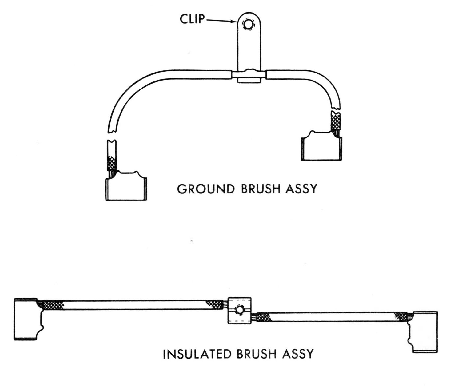
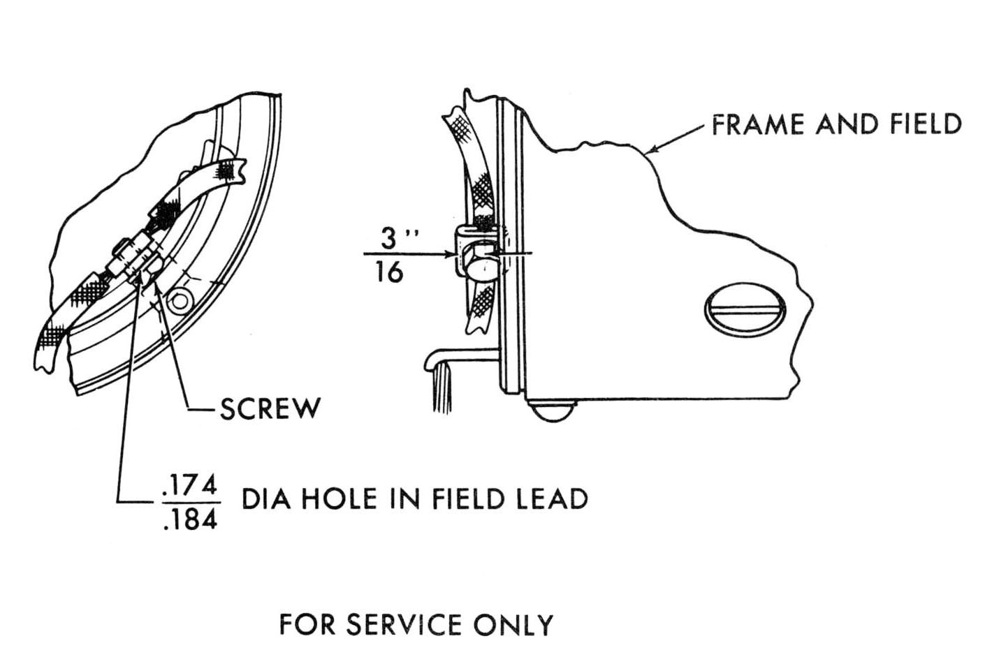
CHRYSLER BUILT STARTING MOTOR BRUSH REPLACEMENT A new starter motor brush service package is available for Chrysler built direct drive starting motors MoPar Part Number 2525529. The package consists of the two ground brushes and a connecting lead with. ground terminal attached to the lead. Two insulated brushes and connecting lead with terminal attached. One number 8 self tapping screw and washer. INSTALLING INSULATED BRUSH SET To install the insulated service brush set, peel the stranded wire of the old brush set at the weld from the series field coil lead. Lay out the hole position by measuring back 3/16 inch from end of series coil lead, on the lead center line. Carefully center punch the intersecting marks and drill�hole with a number 16 drill (.177"). |
|
|
Attach insulated brush set to series field lead with flat washer and number 8 self tapping screw furnished in kit. INSTALLING GROUND BRUSH SET Remove old ground brush set exercising caution to prevent breaking shunt field lead. Remove shunt field lead from old brush set to ensure as much length as possible. Attach shunt field lead to new brush set by making a loop around terminal and soldering leads to terminal. Attach ground brush to field frame with screw. Fold surplus shunt field lead back along brush lead and secure with rubber insulating tape. Service brushes are available through MoPar under the following part numbers:
|
|
|
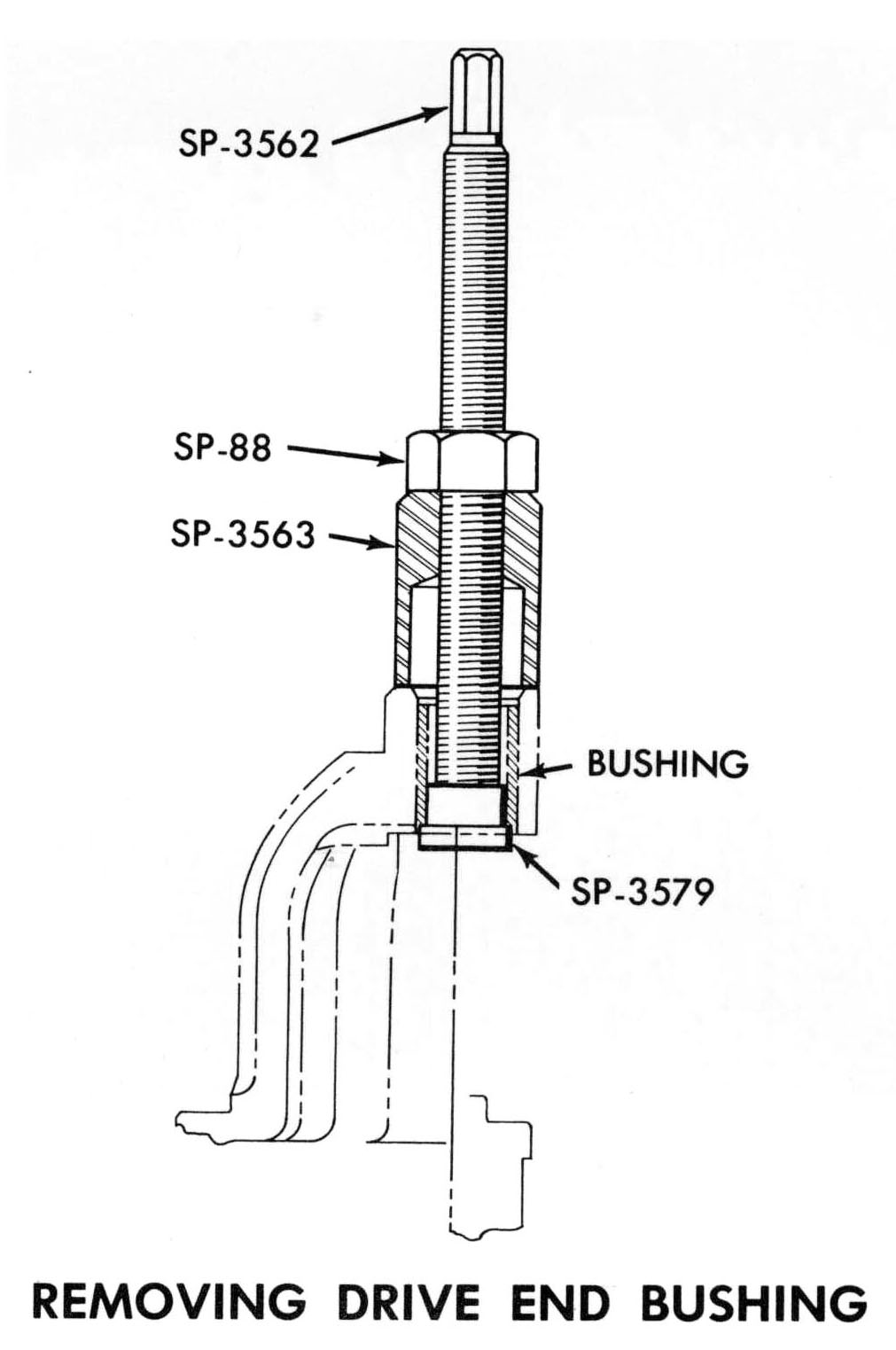
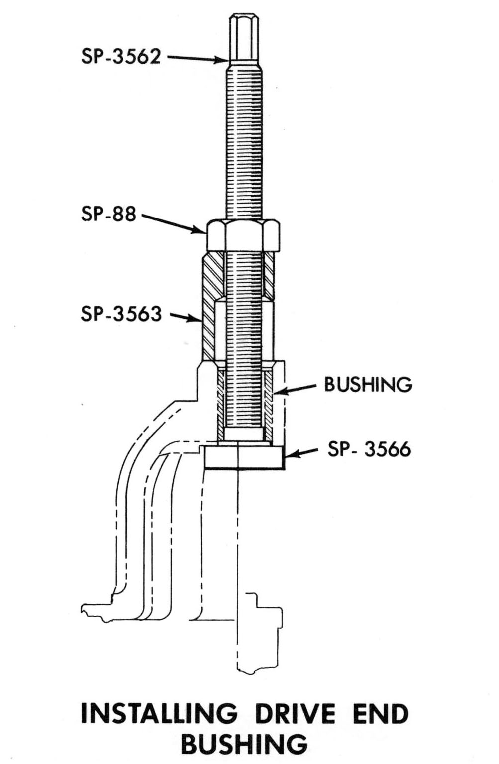
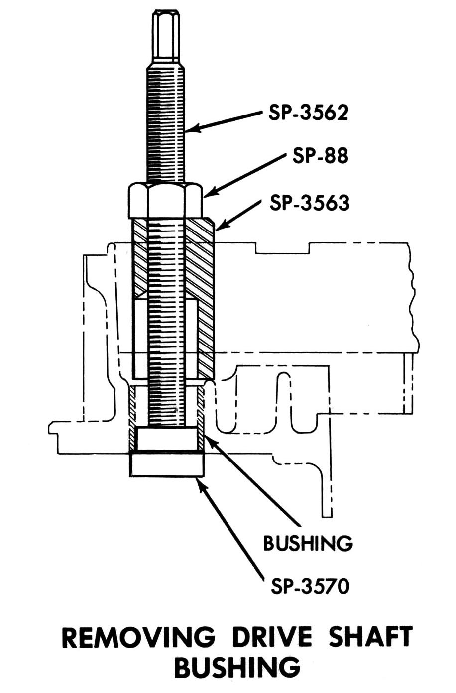
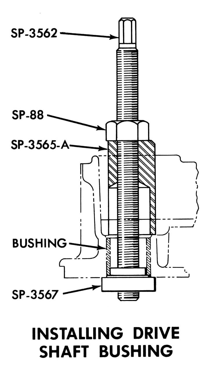
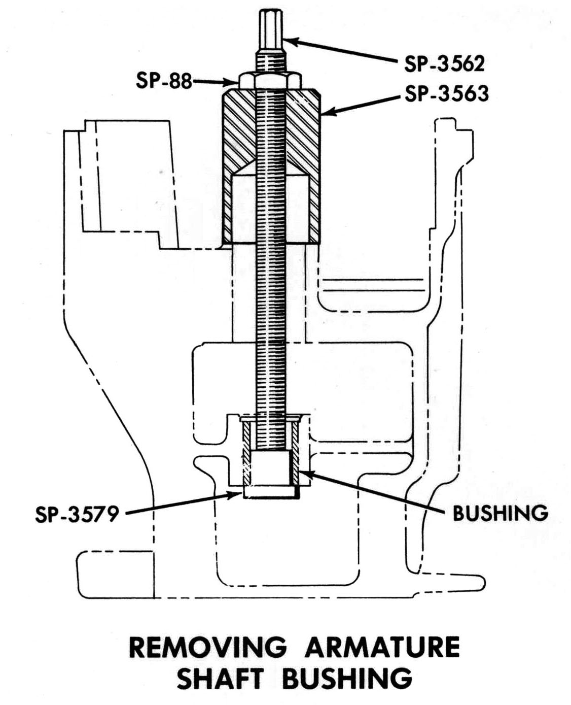
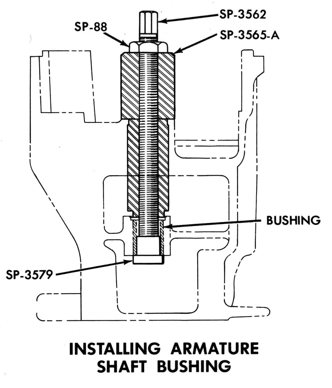
SERVICING STARTING MOTOR BUSHINGS Pre-sized starting motor bushings are available as service bushings. A new tool C-3944 has been designed to remove the old bushings and install the new. No burnishing or reaming is required to fit the pre-sized bushings. The C-3944 tool and its adaptors are designed to service all of the gear reduction motor bushings with the exception of the end head bushing. The end head bushing and end head are serviced as an assembly. The tool is also designed to remove and install the drive end bushing on the direct drive motors. |
|
|
"V" SERIES INSTRUMENTS GENERAL Thermal type gauges and printed circuits used on all "V" series passenger cars. Servicing varies from car to car. Chrysler, Valiant, Dodge 880 and Dart service procedures essentially the same as "T" series. Plymouth, Dodge, and Imperial service procedures for removal, bench testing, and installation are new. |
|
|
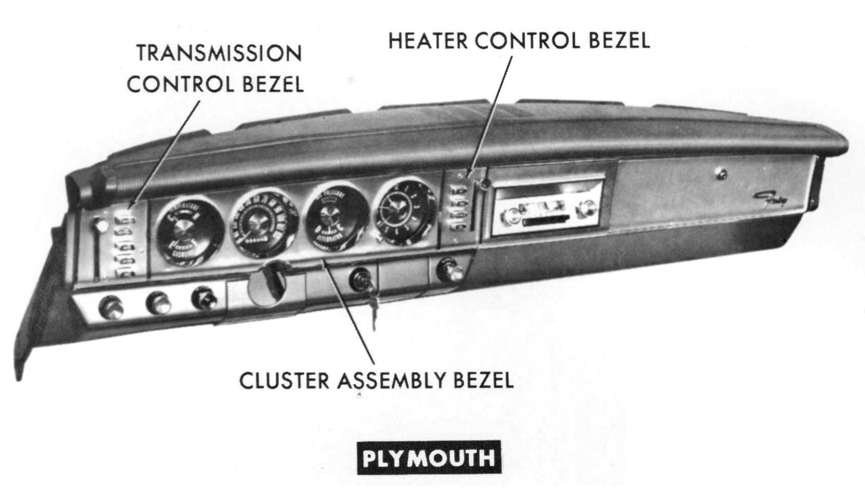
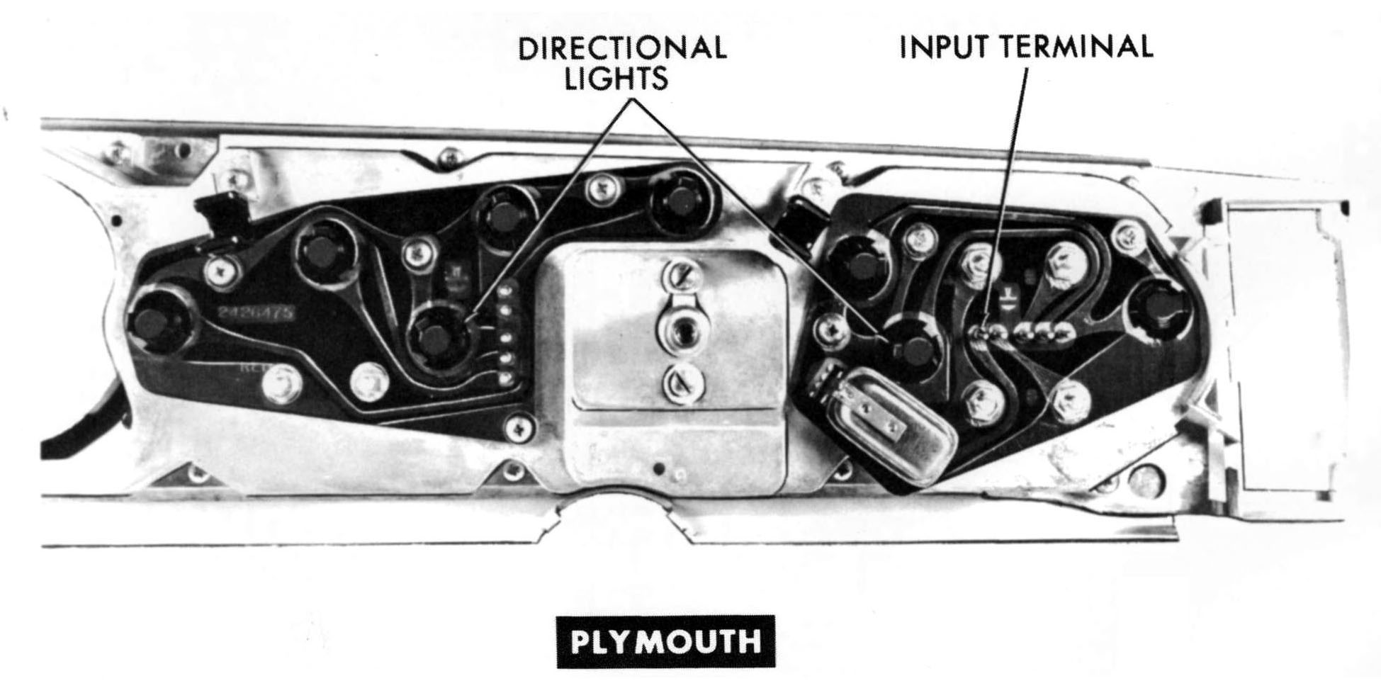
PLYMOUTH INSTRUMENT LIGHTING All indicator and instrument lighting bulbs accessible from below, excepting radio. Radio must be removed to replace bulb. Turn signal bulbs are at bottom of each printed circuit at both sides of speedometer. REMOVING CLUSTER Speedometer cable is disconnected from below. To remove cluster, lever knobs and small bezels must first be removed from transmission and heater controls. Cluster assembly can be rolled back after removal of screws to remove wiring from printed circuit. Heater switch vacuum hose and bowden cable must also be removed to remove cluster assembly. TESTING Input side of voltage limiter for 1964 Plymouth located at connector pin nearest speedometer as viewed when facing rear of printed circuit. |
|
|
CAUTION: Always connect test battery positive lead to input terminal of voltage limiter. Always ground cluster casting when testing gauge operation at bench. |
|
|
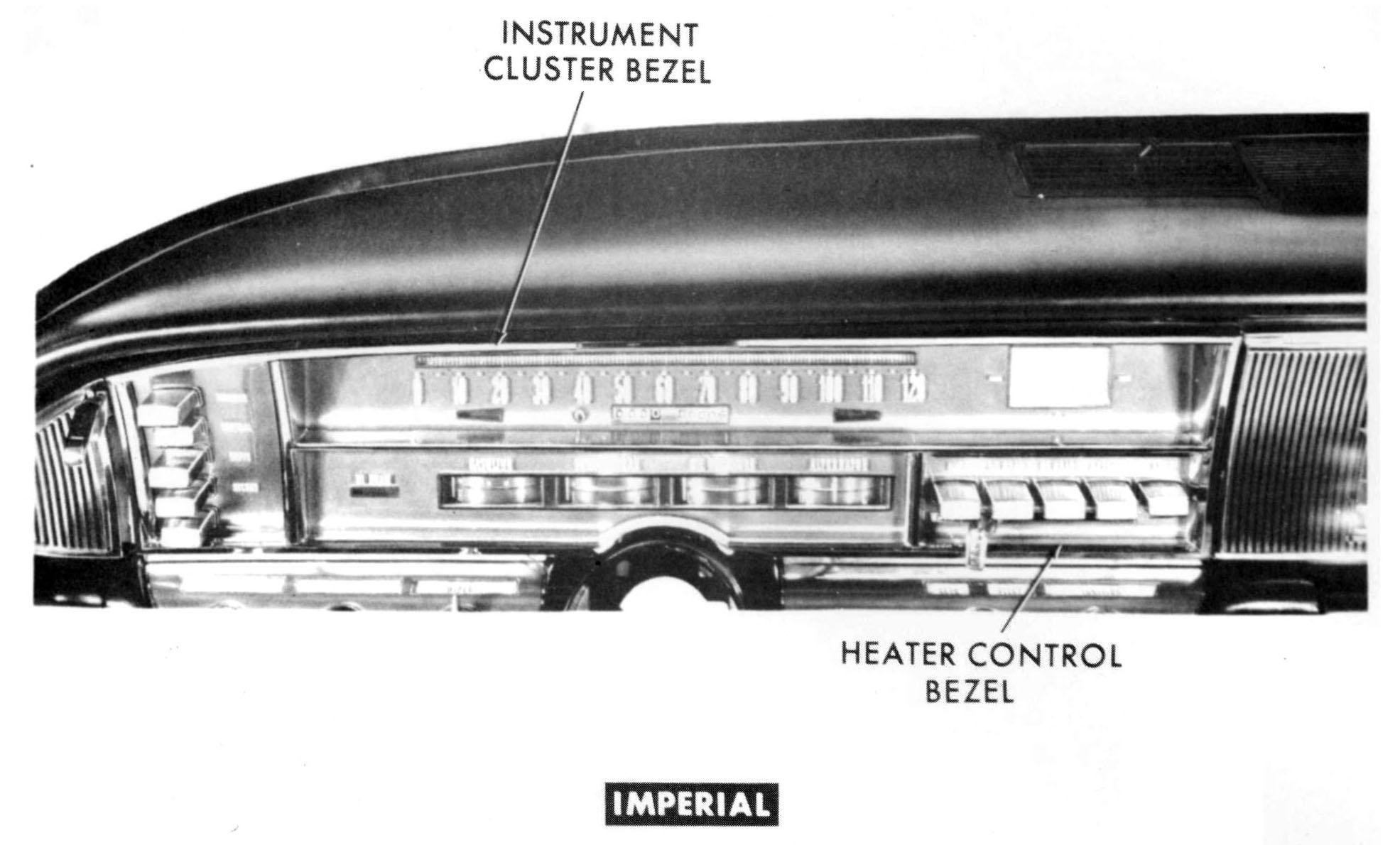
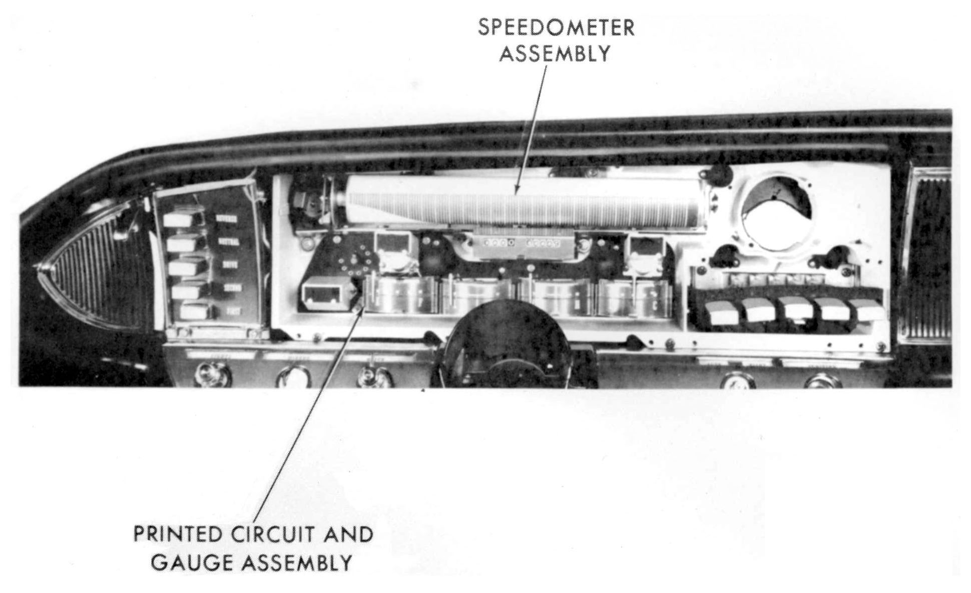
IMPERIAL 1964 "V" series instrument panel completely new. INSTRUMENT LIGHTING Cluster lighting bulbs are accessible from below, exceptIng radio. Radio must be removed to replace bulb. Switch title lenses are iluminated by bulbs next to switches. Remove switch bezel to replace bulbs. |
|
|
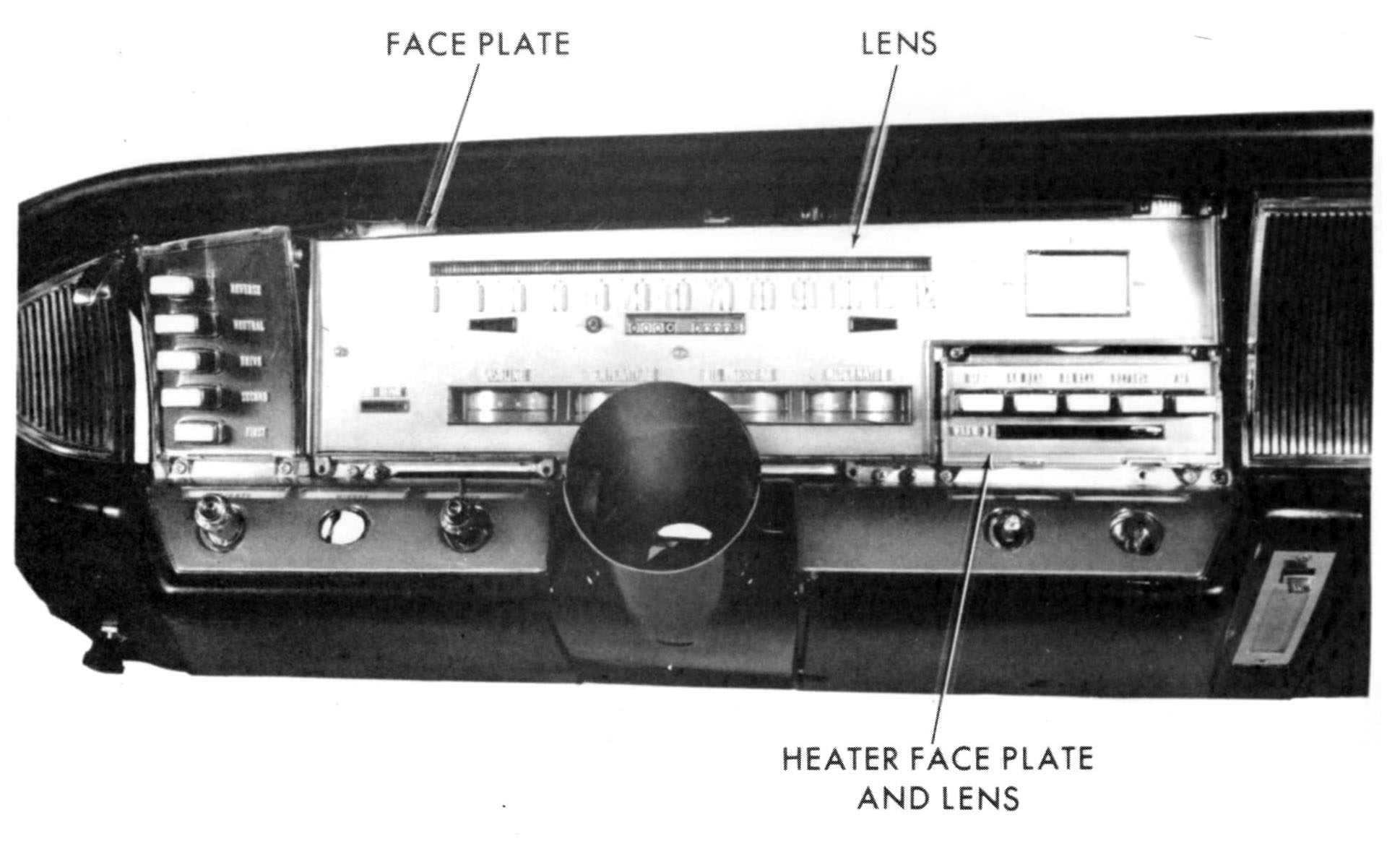
SERVICING CLUSTER COMPONENTS Cluster not serviced as assembly. Three main sub-assemblies are covered by a single bezel. Remove as follows:
|
|
|
|
|
|
|
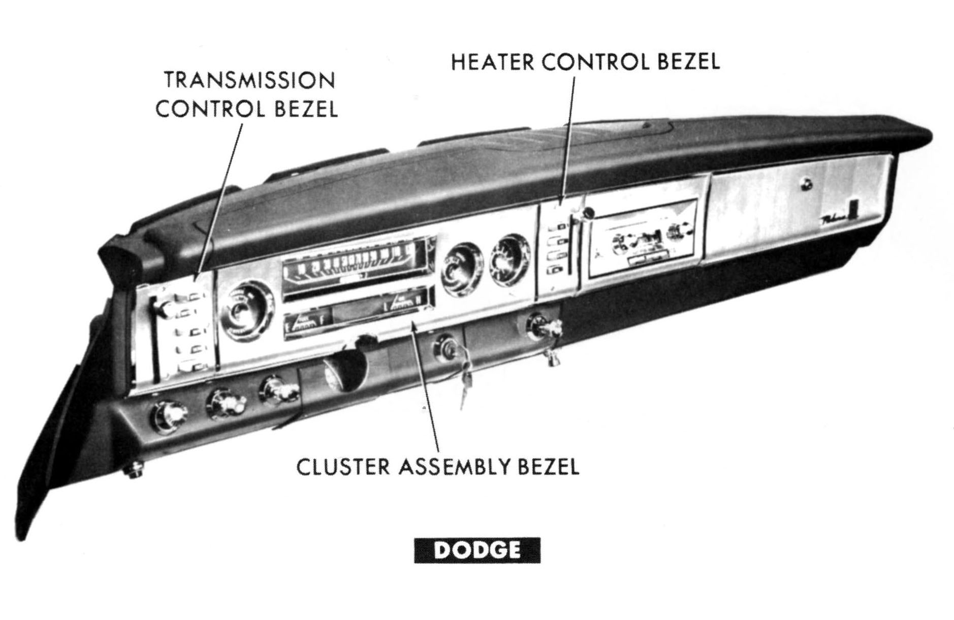
DODGE 1964 "V" Series Dodge instrument panel completely new. PANEL LIGHTING Accessible from below excepting:
|
|
|
INSTRUMENT CLUSTER Serviced as an assembly, must be removed from car to service instruments. Remove knobs and bezels from temperature and transmission controls. Drop steering column for clearance. |
|
|
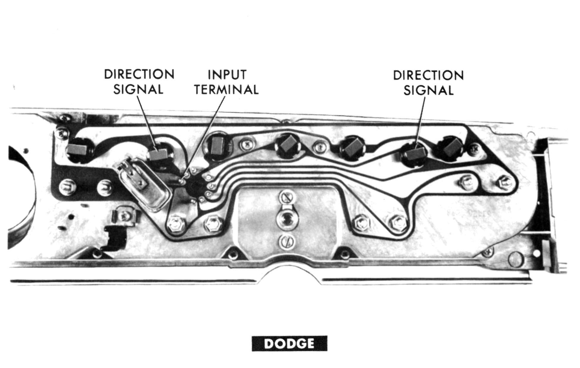
The input terminal pin is next to the voltage limiter. Positive battery test lead must be connected to this pin when testing at bench. NOTE: Always ground casting when testing at bench. |
|
|
Having trouble with printouts coming out way too small, or pieces of a document printing acro ss sev eral page s? Then go to our "How To Print Imperial Literature" page to learn how to print an item at the size you'd like. |
This page was last updated 13 January 2010. Send us your feedback, and come join the Imperial Mailing List - Online Car Club
