|
BBS SINGLE BARREL CARBURETOR CHANGES
- FOR BEVER HOT STARTING -
- Main discharge nozzles have upward angle. Venturi position raised accordingly. (Improves hot starting � less fuel dribbling).
- New float valve and seat � has thin rubber coated metal gasket for better sealing, and shorter redesigned orifice for less fuel aeration.
- New float design for greater float drop.
|

|
|
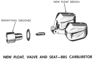
FLOAT, VALVE AND SEAT-BBS CARBURETOR
- Seat fitting identified by grooves.
- Shape of float permits greater float drop.
- Less "burbling" reduces fuel aeration.
- Can be used on prior BBS Carburetors (new type gasket must be used with new seat).
|
|
|
BBS SINGLE BARREL CARBURETOR CHANGES
- Size of air bleed hole in choke valve increased - admits more air, reduces overchoking.
- Bottom accelerating pump bore cone shaped, eliminates need for accelerating pump inlet ball retainer.
|

|
|
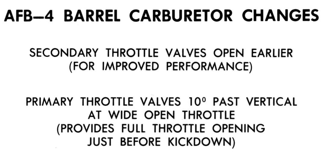
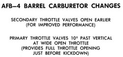
AFB - FOUR BARREL CARBURETOR CHANGES
- Secondary throttle valves start to open earlier as primary valves are opened. (For improved performance)
- Primary throttle valves at verti�al just before kickdown of transmission and 10 degrees past vertical after kick- down. (Assures full throttle performance in direct drive).
|
|
|
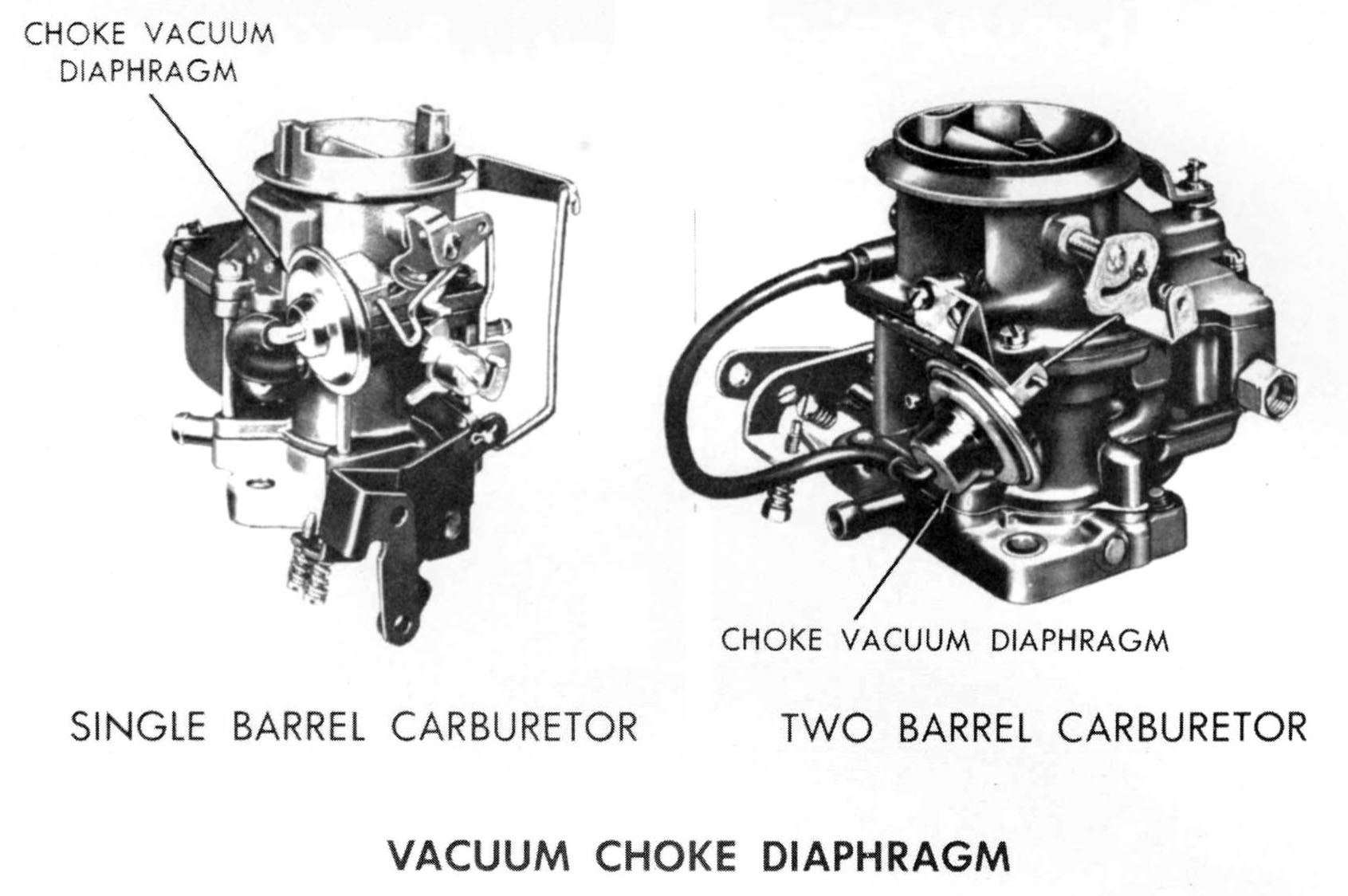
VACUUM CHOKE DIAPHRAGM
- Replaces choke piston on all carburetors.
- Sealed chamber, not repairable, serviced by replacement only.
- Vacuum works against diaphragm spring.
- Eliminates choke piston sticking.
- Results in new procedures for:
- Fast Idle cain positioning.
- Choke vacuum kick adjustment.
- Checking choke operating clearance.
- Fast idle speed adjustment.
|

|
|
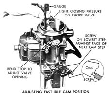
ADJUSTING FAST IDLE CAM POSITION
(ALL CARBURETORS EXCEPT 4BBL)
- Position idle screw on lowest step of cam.
- Should be slight drag on gauge with light closing pressure on choke.
Adjustment:
- BBD (2 bbl.) - bend stop on choke shaft lever.
- WW3 and WWC3 (2 bbl.) - bend fast idle rod.
- BBS and Holley (1 bbl.) - bend fast idle rod.
|
|
|
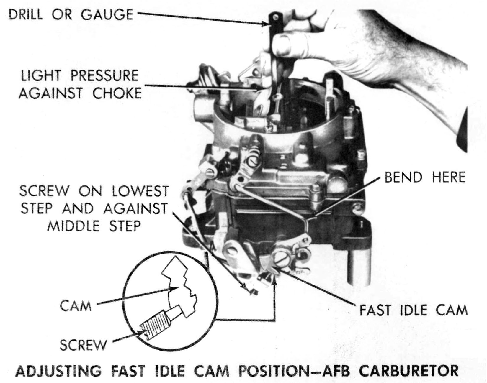
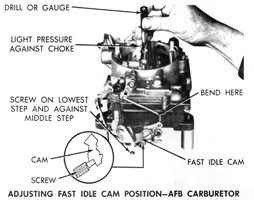
ADJUSTING FAST IDLE CAM POSITION - AFB - 4BBL
- Open throttle to allow fast idle screw to clear cam.
- Insert gauge between choke valve and air horn wall.
- Close throttle until screw hits cam.
- Bend fast idle rod so screw lightly contacts middle step but slides to bottom step. Screw must ride against shoulder of middle step.
- Spring loaded fast idle cam makes this procedure necessary.
|
|
|
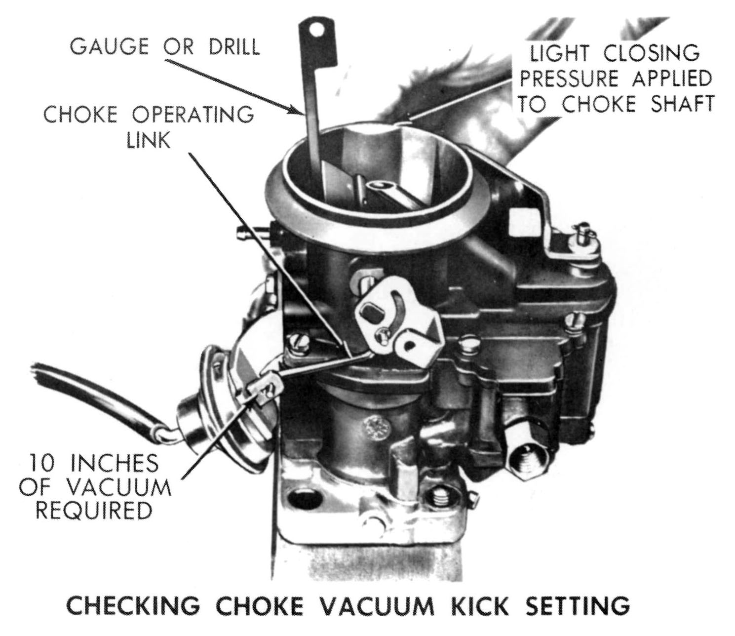
CHOKE VACUUM KICK ADJUSTMENT - (All Carburetors)
- Can be done on or off vehicle.
- Must be checked with engine not running.
- Open throttle to let choke close.
- Energize vacuum diaphragm with minimum of 10" vacuum (use distributor test machine or another engine as vacuum source).
- Insert gauge between choke valve and air horn and apply light closing pressure.
- If slight drag is not felt at gauge, adjust by removing and bending choke operating link. (Link must be removed to avoid damage to diaphragm or lever slot while bending).
|

|
|
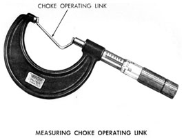
MEASURING CHOKE OPERATING LINK (All Carburetors)
- Measure change in link length with 2" micrometer.
- .010" change in link length means .015" change at choke opening.
|
|
|
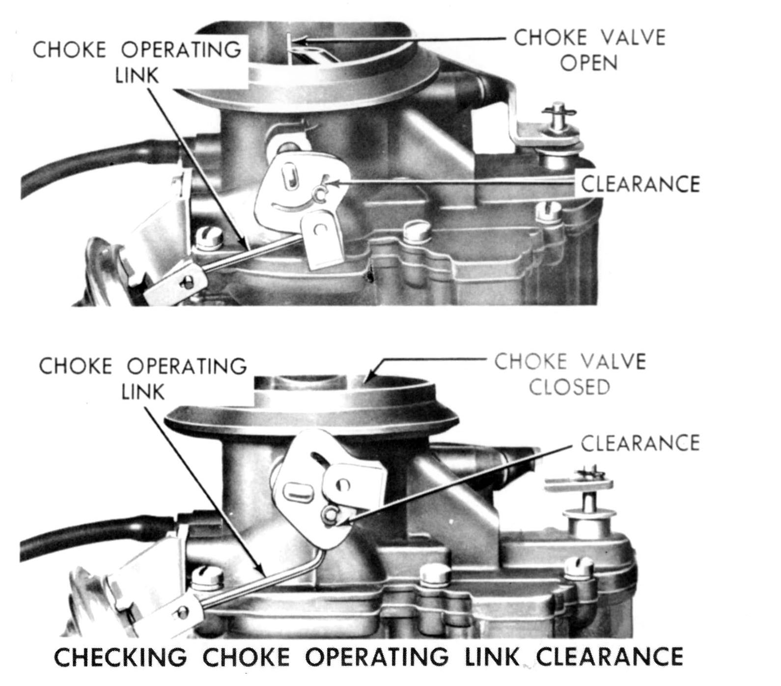
CHECKING CHOKE OPERATING LINK CLEARANCE (All Carburetors)
- With no vacuum at diaphragm, end clearance must exist at slot when choke is fully opened or fully closed. (This is necessary to allow choke full operating range).
- If not satisfactory, recheck vacuum kick adjustment.
- If choke is not free, check for bind at choke operating link.
|

|
|
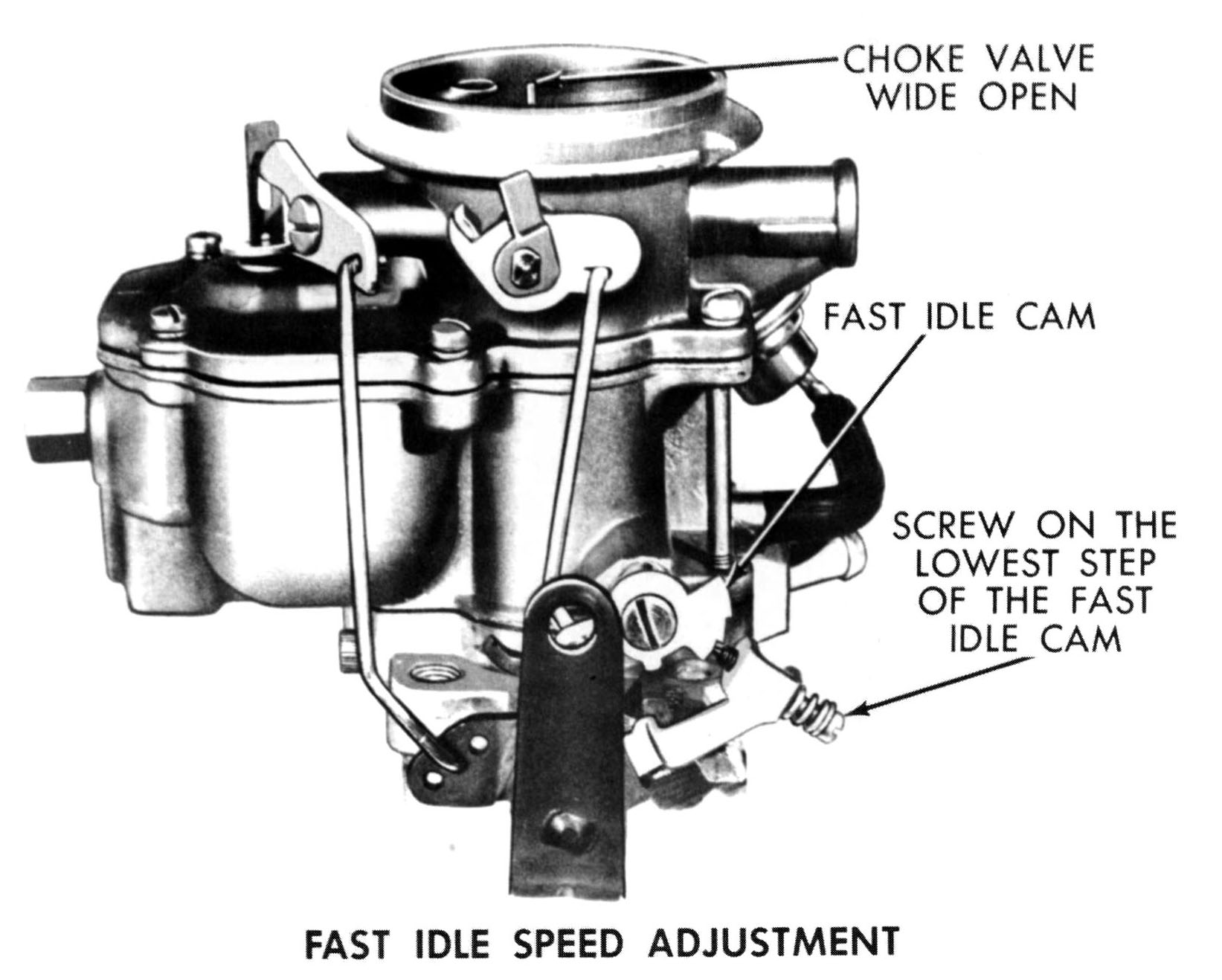
FAST IDLE SPEED ADJUSTMENT (All Carburetors)
- With engine at operating temperature, connect tachometer - set curb idle speed.
- Open throttle slightly (transmission in neutral and engine running).
- Close choke valve 20 degrees and allow throttle to close. Return choke to open position.
- Fast idle screw should be on lowest step of cam.
- With engine at normal operating temperature, adjust fast idle speed screw to 700 RPM engine speed (reposition cam and throttle after each screw adjustment for accuracy).
|

|
|
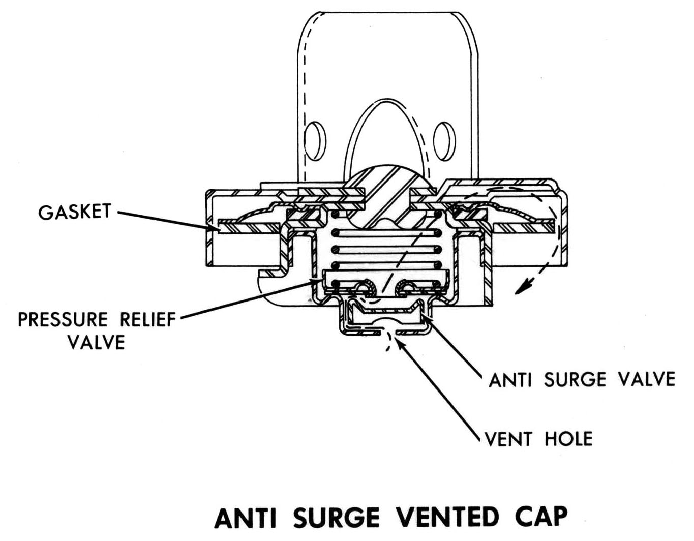
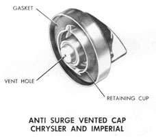
CHRYSLER AND IMPERIAL - ANTI SURGE VENTED CAP
- Eliminates spillage caused by fuel surge during acceleration. Other non vented caps will not fit. (Their retaining cups are too large for retaining cam on Chrysler and Imperial filler tubes).
|
|
|
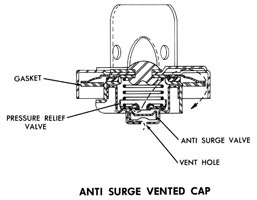
ANTI SURGE VENTED CAP
- Surge of fuel closes anti surge valve, which normally hangs free.
- Pressure relief valve relieves pressure if any occurs in tank.
- Vent passages protected by cap.
|
|