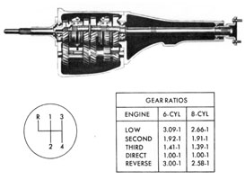
- This is a Chrysler-built four-speed manual transmission, fully synchronized in all four forward speeds, with two strut-type synchronizers.
- There are two gear ratio versions - one for 6-cylinder models and one for V-8�s.
- It is available in all models except Imperial and New Yorker.
- The transmission case and extension housing are cast iron.
- The main drive pinion and the mainshaft turn in heavy duty ball bearings, including the rear bearing in the extension.
- The cluster gear turns on a double row of rollers in each end, and rollers are used in the pilot bearing.
The reverse idler is a sliding gear, and turns on a bronze bushing pressed into the gear.
Two new special tools are released for servicing this unit - a cluster gear assembly arbor and a selector lever alignment tool.
|
|
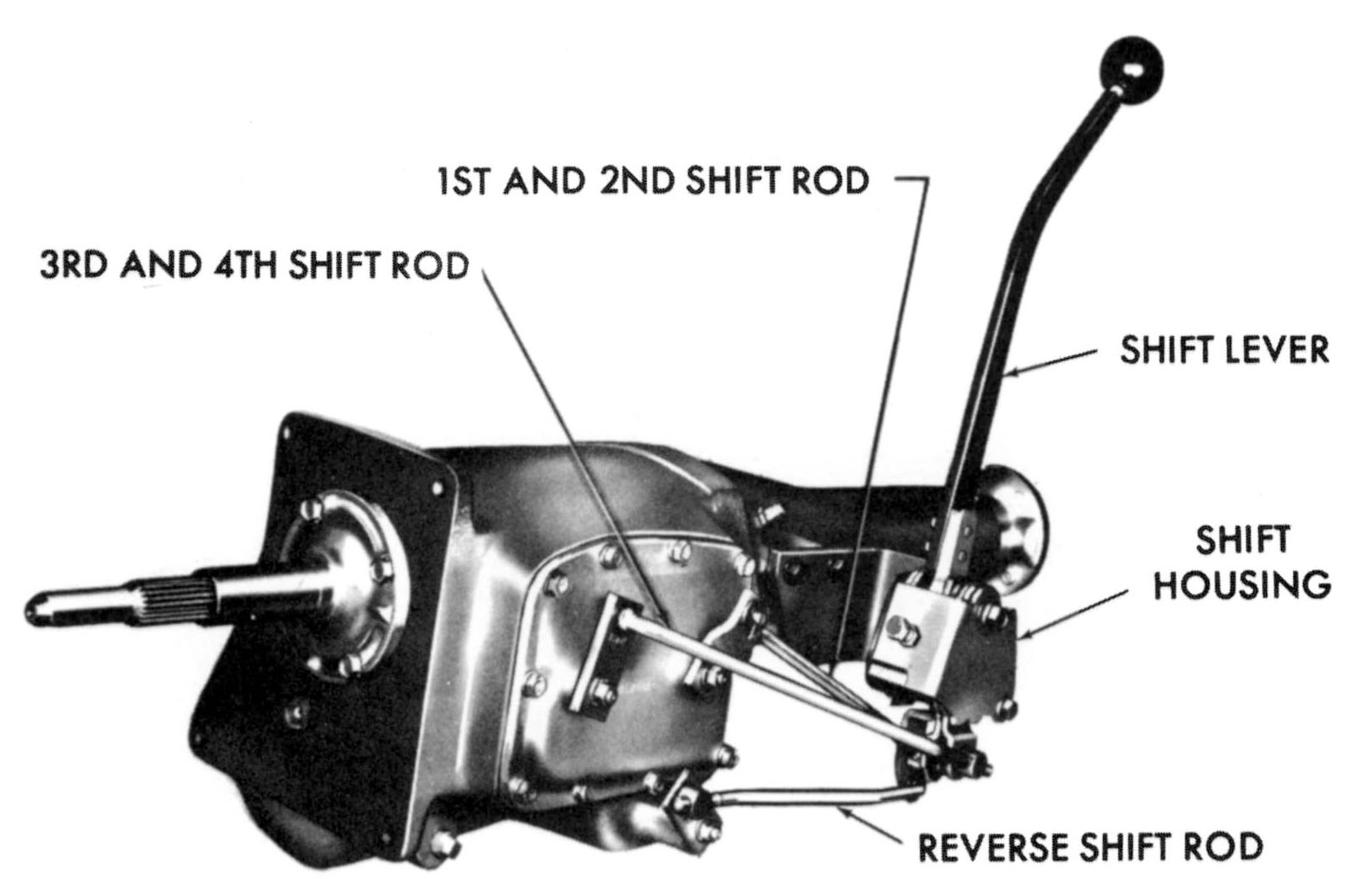
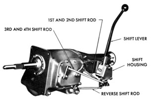
- Gear selections are made through a transmission-mounted Hurst-Campbell linkage.
- All parts are of rigid construction.
- A threaded swivel on one end of each shift rod provides positive adjustment.
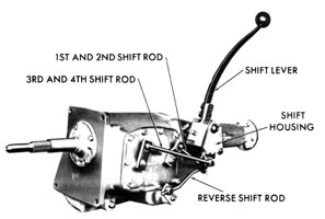
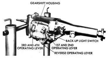
- The transmission operating levers for the four forward speeds mount on shafts through a removable cover on the left side of the transmission, case.
- The reverse operating lever shaft extends through the case casting below the shift cover toward the rear.
- Silencing grommets are not used in the operating levers.
This view shows the assembly used in the 122-inch wheelbase models, with the gear selector mechanism mounted on a bracket extending outward from the left side of the extension housing.
|
|
- In Valiant, Dart, Plymouth and Dodge the gear selector mechanism mounts on a flat plate against the extension housing.
- The Plymouth and Dodge assembly is shown in this view.
- The Valiant and Dart assembly is very similar in appearance to the Plymouth and Dodge unit shown in this view.
|
|
|
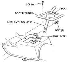
Before the transmission can be removed, it is necessary to remove the shift control lever and dust boot from the console trim plate, proceeding as follows:
- Remove the retaining screws from the boot retainer. The number of screws varies from 3 to 8, depending on the model. On Plymouth and Dodge, the entire console must be removed, which involves removing the front seats, the control lever knob, and the console retaining screws.
- Slide the boot and boot retainer up the control lever far enough to expose the stub lever.
- Remove the two bolts that attach the control lever to the stub lever, and remove the control lever, boot and boot retainer.
|
|
|
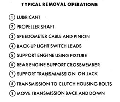
TYPICAL REMOVAL OPERATIONS
- Drain the transmission lubricant.
- Disconnect the propeller shaft from the output shaft flange. Remove the speedometer cable and pinion from the extension.
- Disconnect the leads from the back-up light switch.
- Support the engine with the appropriate engine support fixture.
- Remove the rear engine support crossmember.
- Support the transmission on a transmission jack.
- Remove the transmission to clutch hoising retaining bolts.
- Move the transmission rearward until the drive pinion clears the clutch hub, and lower the transmission. On some models it is necessary to rotate the transmission counterclockwise to permit the gear selector stub lever to clear the transmission hump.
- Thoroughly clean the outside of the transmission before disassembly.
|
|
|
SHIFT LINKAGE REMOVAL
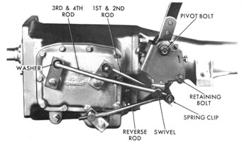
- The three shift rods are attached at each end to their respective levers by two flat washers and a spring clip except Valiant and Dart, where washers are used only at the swivel ends.
- The gear selector assembly is attached to the mounting bracket or plate by its pivot bolt and a retaining bolt. Remove the pivot bolt and the retaining bolt, and remove the gear selector assembly.
- Remove the gear selector assembly mounting bracket (Chrysler or 880) or the mounting plate (Valiant, Plymouth, Dart or Dodge) from the extension housing.
|
|
|
DISASSEMBLY OF THE TRANSMISSION
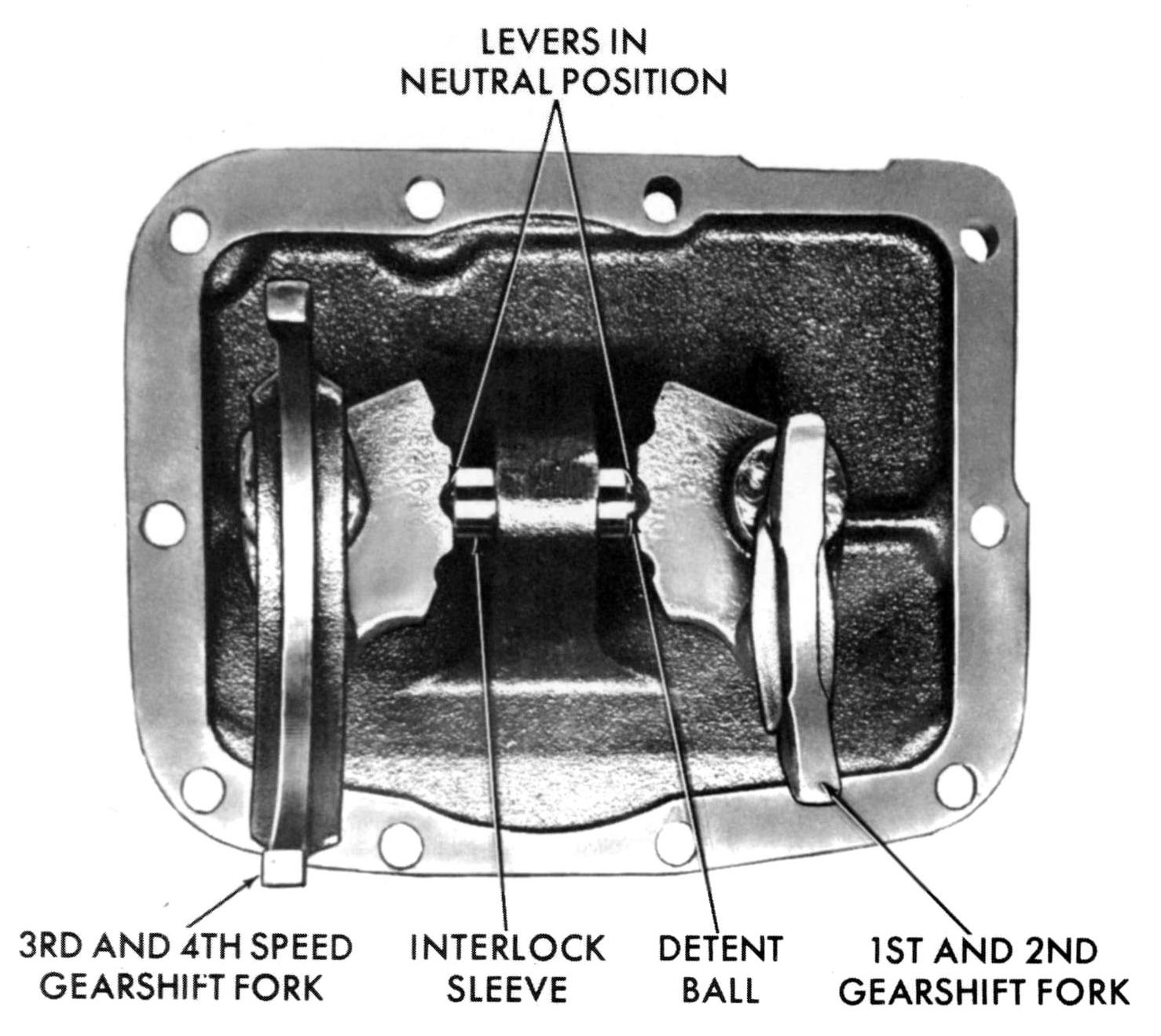
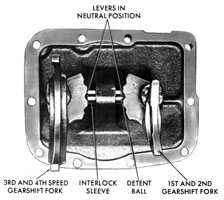
- Remove the transmission case cover assembly from the left side of the case, and discard the gasket.
- Remove the two forward speed shift forks from the clutch sleeves.
- Remove the reverse operating lever.
- Remove the back-up light switch, if so equipped, and discard the gasket.
- Remove the transmission output shaft flange.
|
|
|
The transmission case cover assembly, with shifter shafts and interlock assembly, is typical, and is serviced in the conventional manner.
|
|
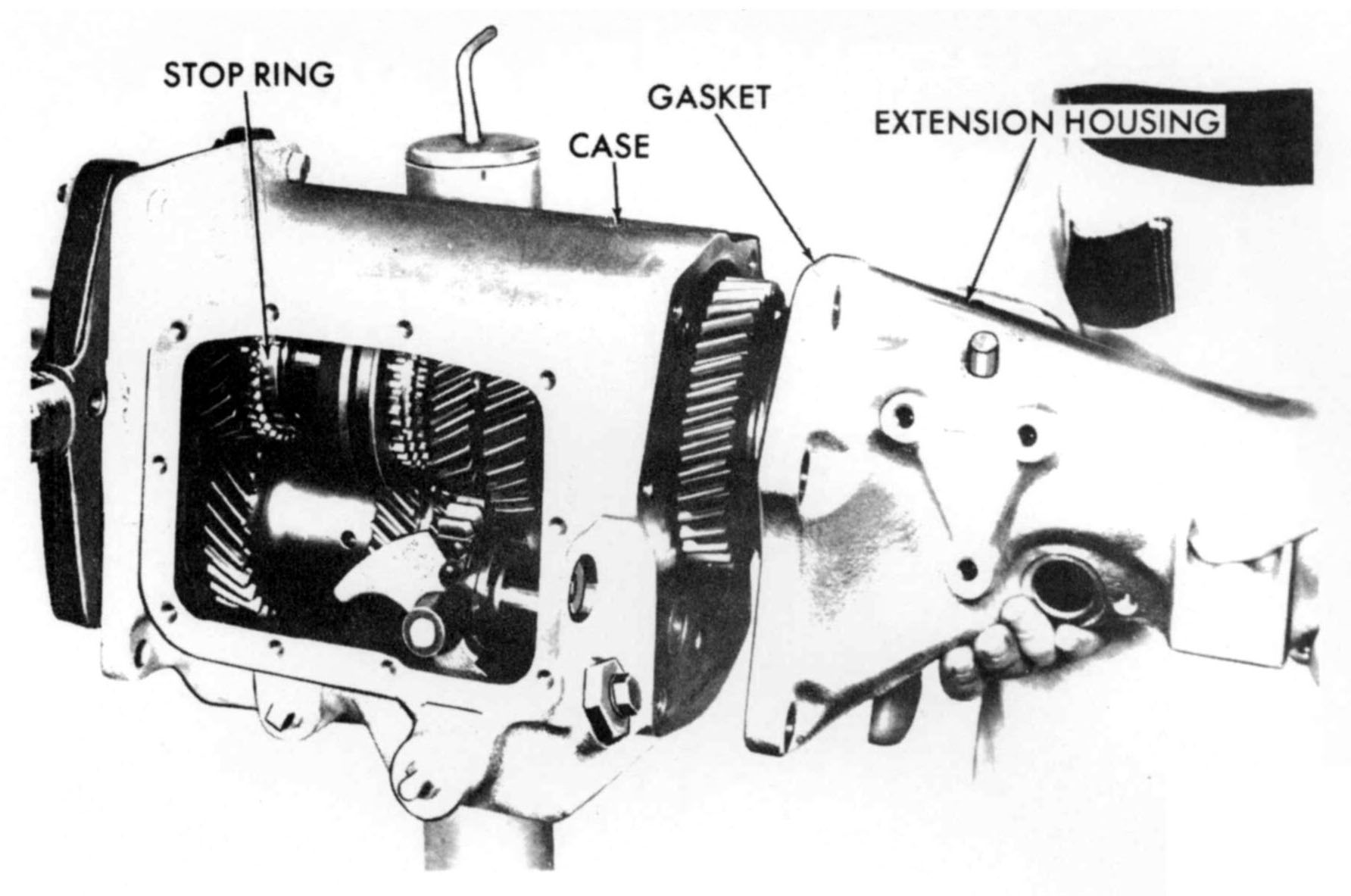
- Remove the extension to case retaining bolts.
- Tap rearward on the extension until the extension comes free of the transmission case and carefully remove the extension and transmission mainshaft assembly as an assembly.
- If the third and fourth speed synchronizer front stop ring remains on the hub of the main drive pinion remove the stop ring.
|

|
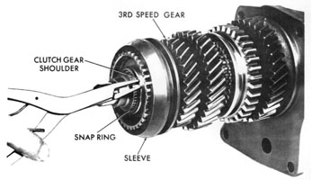
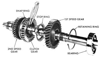
- Remove the third and fourth speed synchronizer clutch gear snap ring from the front of the mainshaft.
- Slide the front synchronizer assembly and the third speed gear forward off the mainshaft.
- This synchronizer is a typical strut- type synchronizer, and is serviced in the conventional manner.
|
|
|
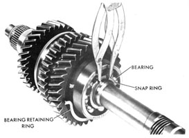
The intermediate bearing is located in a bearing support cast integrally in the front of the extension housing casting. The bearing is located by an internal expanding retaining ring.
- Using narrow-nosed pliers, release the retaining ring and tap the mainshaft assembly forward out of the extension housing. The rear seal and bearing in the extension housing are typical, except that the bearing is removed from the mainshaft using an arbor press.
|

|
|
Remove the intermediate bearing snap ring from back of the bearing on the mainshaft.
|
|
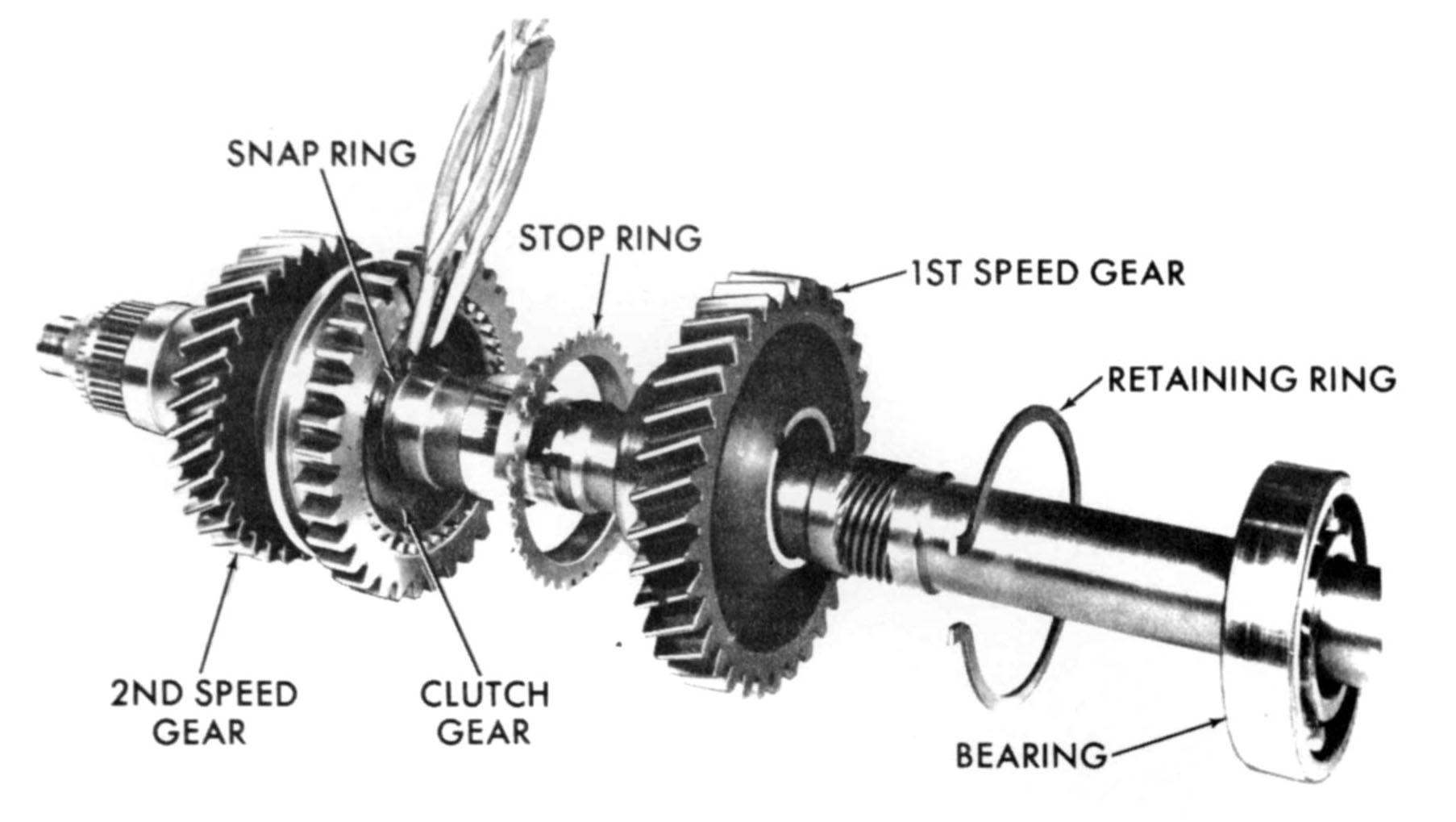
- Install the mainshaft assembly in an arbor press, front end down, with the arbor plates supporting the front face of the first speed gear, and press the mainshaft out of the intermediate bearing.
- Remove the intermediate bearing, retaining ring, first speed gear and first speed synchronizer stop ring.
- Remove the rear synchronizer snap ring from the mainshaft and remove the synchronizer assembly and the second speed gear. This synchronizer is a typical strut-type synchronizer except that its clutch sleeve, in addition to having a groove for the first and second speed shift fork, has a set of gear teeth that the reverse slider gear meshes with in reverse.
|
|
|
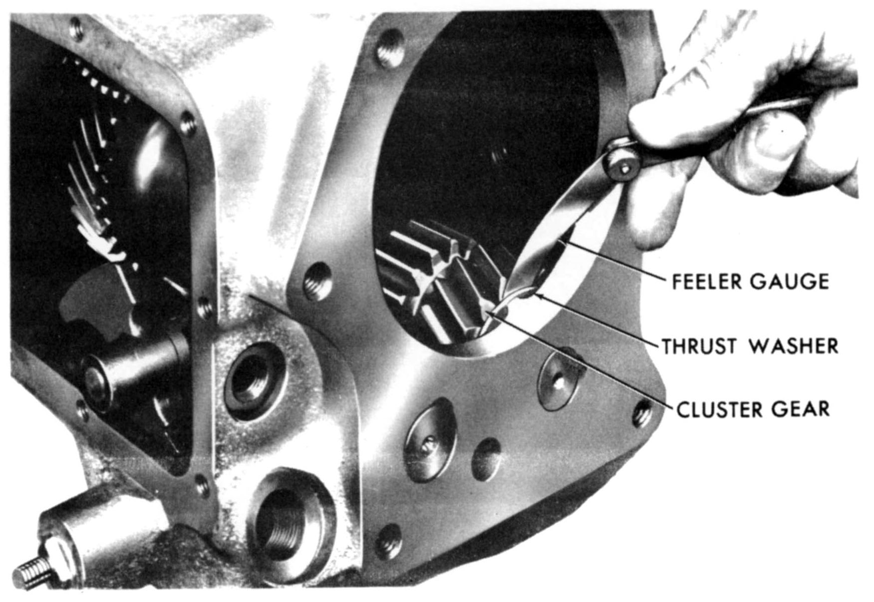
Measure cluster gear end play, using feeler gauge between the cluster gear and the rear thrust washer. The specified limits are .005 to .025 inches. If end play exceeds these limits, new thrust washers should be installed when reassembling the transmission.
|

|
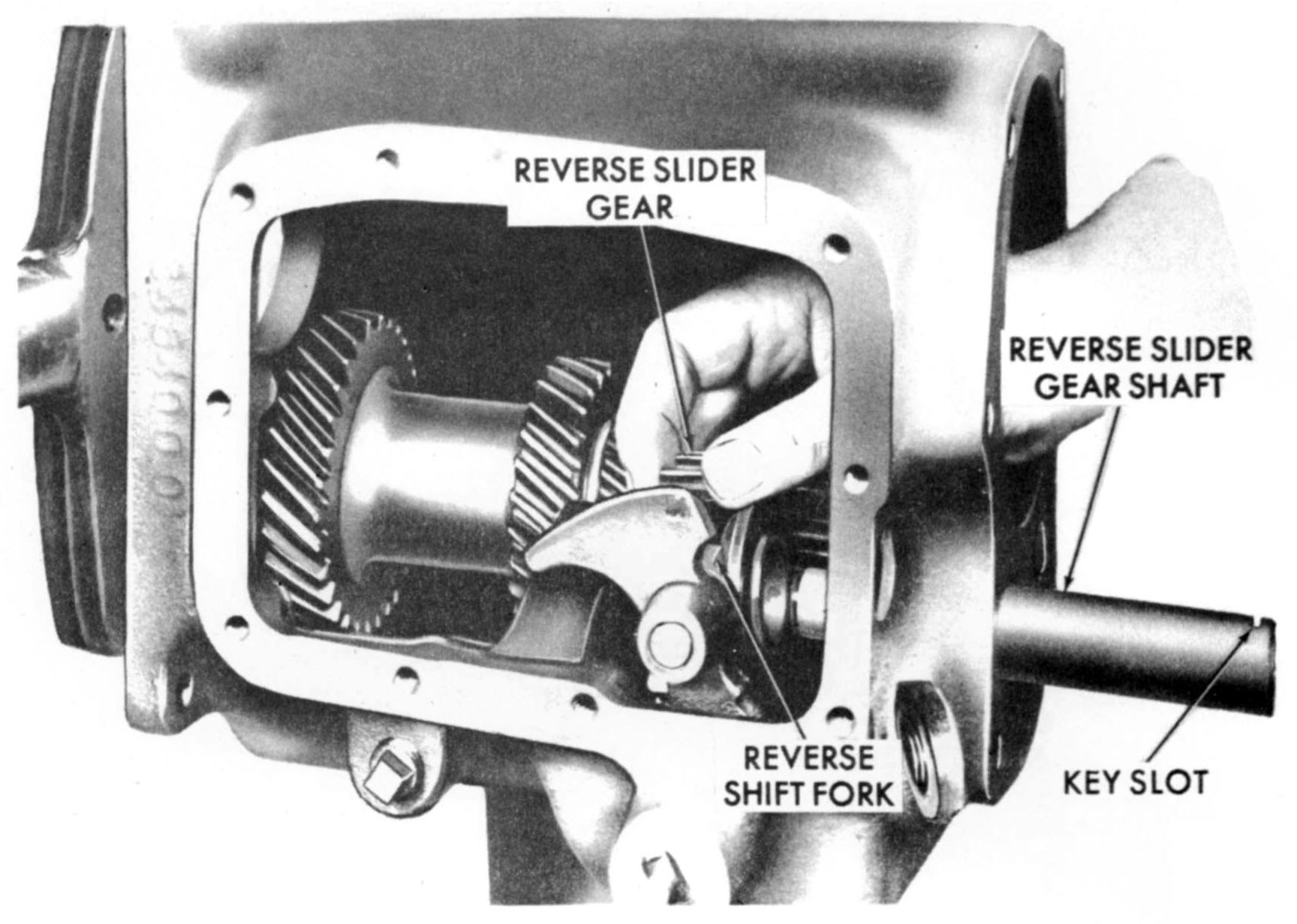
- Using a suitable drift, drive the reverse slider gear shaft rearward out of the case, removing the Woodruff key from the rear of the shaft as it clears the case.
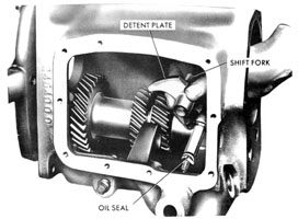
- Remove the reverse detent retainer and plug as an assembly from its bore just below the back-up light switch. Discard the retainer gasket. Remove the detent spring from its bore in the retainer. The detent ball will probably have fallen into the bottom of the transmission case.
|

|
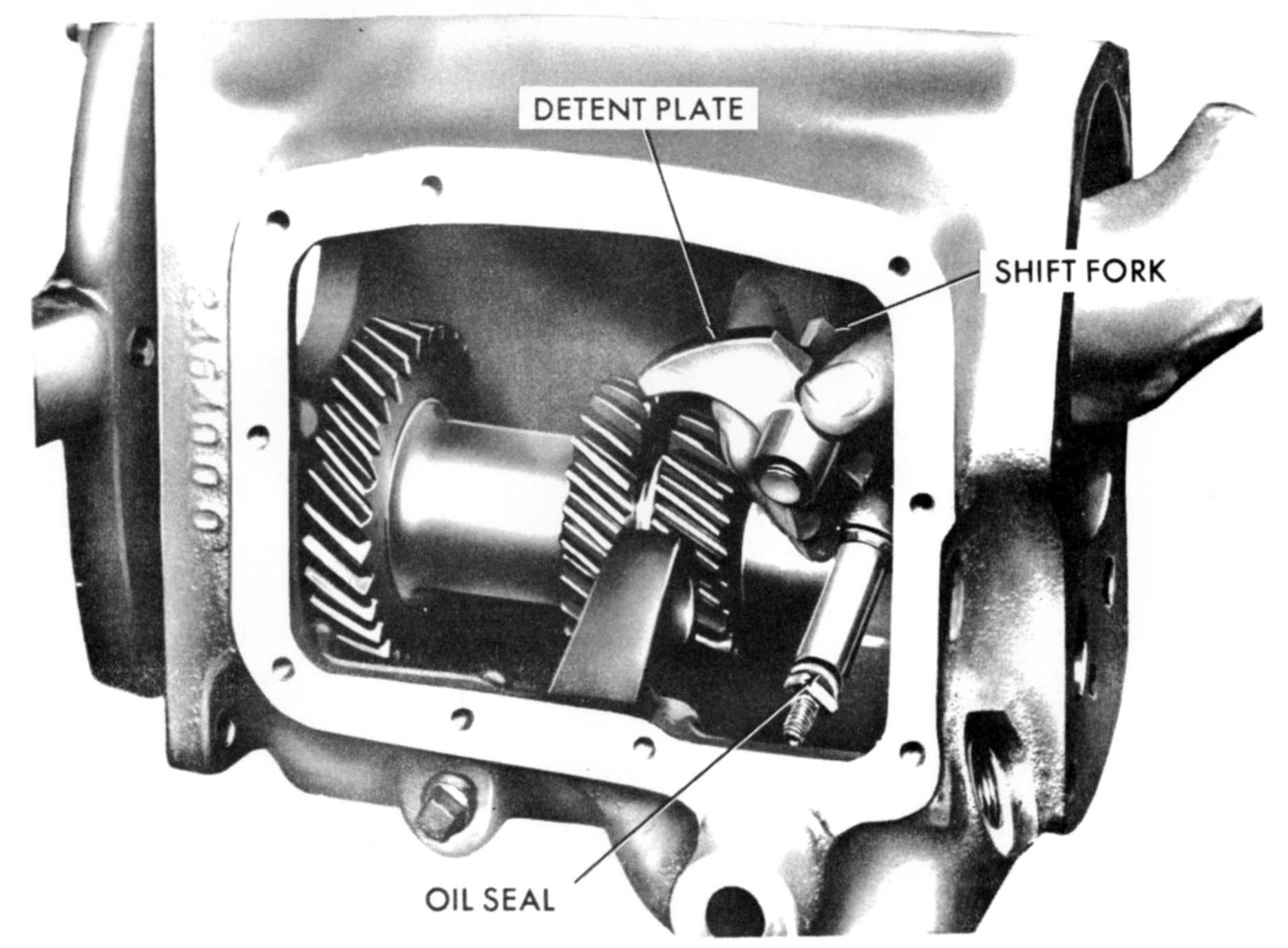
- Remove the reverse shift fork from the shifter shaft detent lever.
- Carefully slide the reverse shifter shaft assembly through into the case, and remove. Discard the 0- ring from the shifter shaft.
|
|
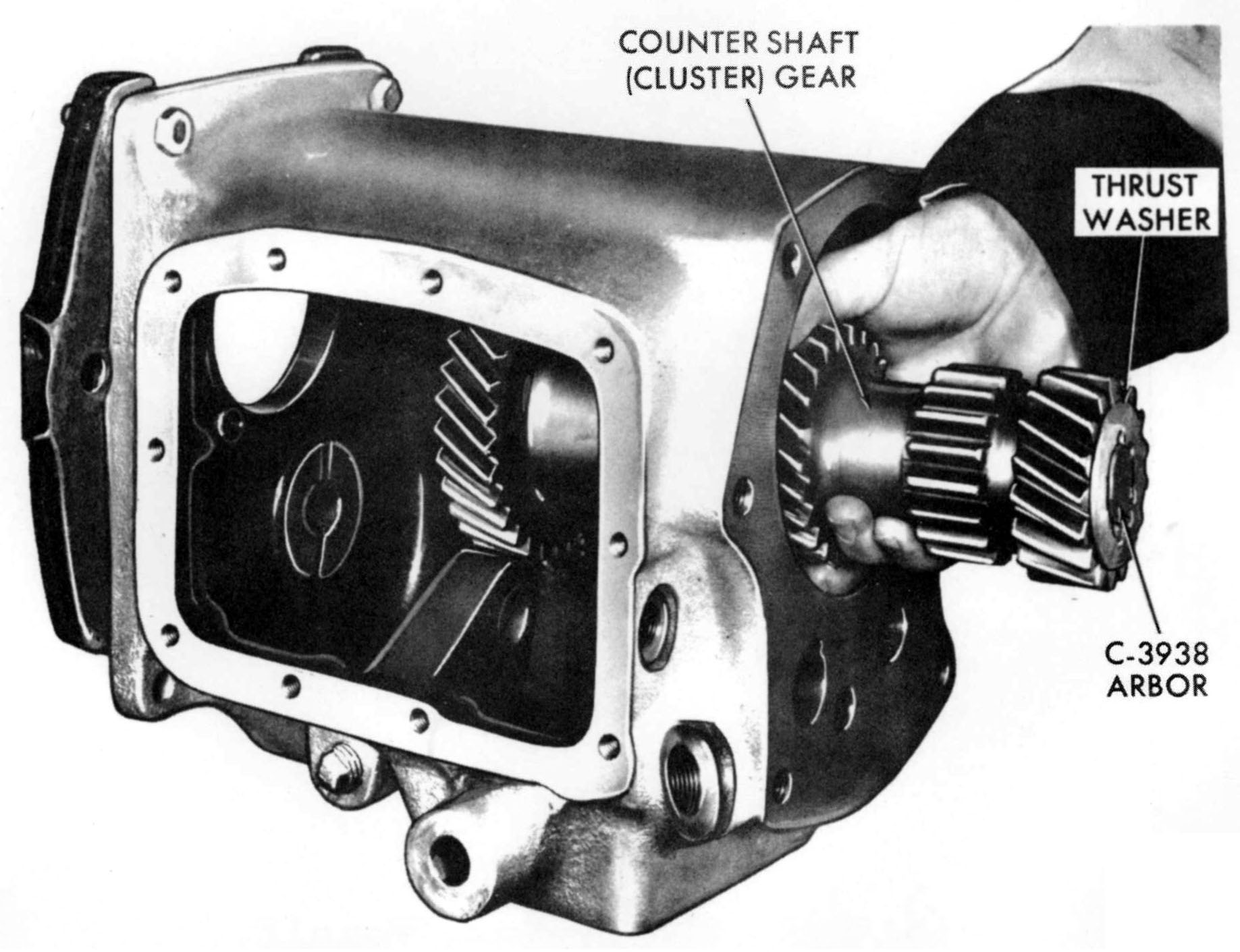
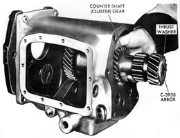
- To remove the main drive pinion assembly, it is necessary first to drop the cluster gear assembly, using assembly arbor C-3938 (a new special tool).
- Remove the pinion retainer and discard its gasket. The pinion retainer seal is serviced in the usual manner.
- Remove the large snap ring from the outer race of the pinion bearing (against the front of the case), and drive the bearing rearward through its bore in the case.
The bearing is a tight press fit on the pinion shaft, and should not be removed unless some one of the parts is to be replaced.
If the bearing is pressed off, a new oil slinger should be installed with the new bearing, with the offset toward the pinion gear. Also, the bearing snap ring on the pinion shaft in front of the bearing is selective, to provide minimum end play (not to exceed .006 inch).
|

|
|
Assembly arbor C-3938 makes it possible to remove and install the entire cluster gear assembly as an assembly, including the front and rear thrust washers, and facilitates installation of the bearings and spacers in the cluster gear.
The cluster gear assembly is typical in design and service procedures.
|
|
|
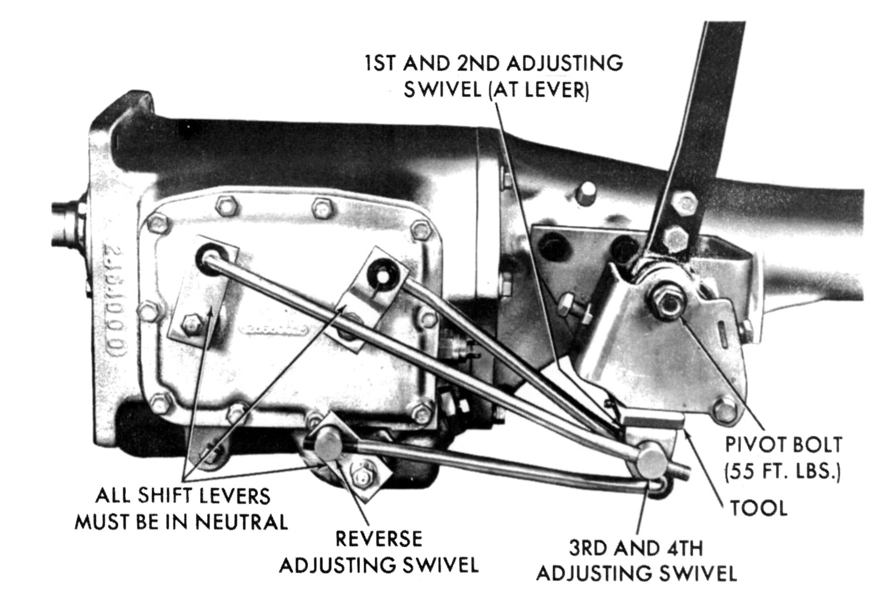
SHIFT ROD ADJUSTMENT
- Shift the transmission into neutral.
- Disconnect each shift rod at its swivel end.
- Install the selector lever alignment tool C-359l (a new special service tool) to position all three selector levers precisely in Neutral.
- Adjust the length of each rod by turning its swivel in or out until the swivel stub enters freely into its hole in the lever. Reconnect each rod as it is adjusted.
- Remove the alignment tool.
|

|
|
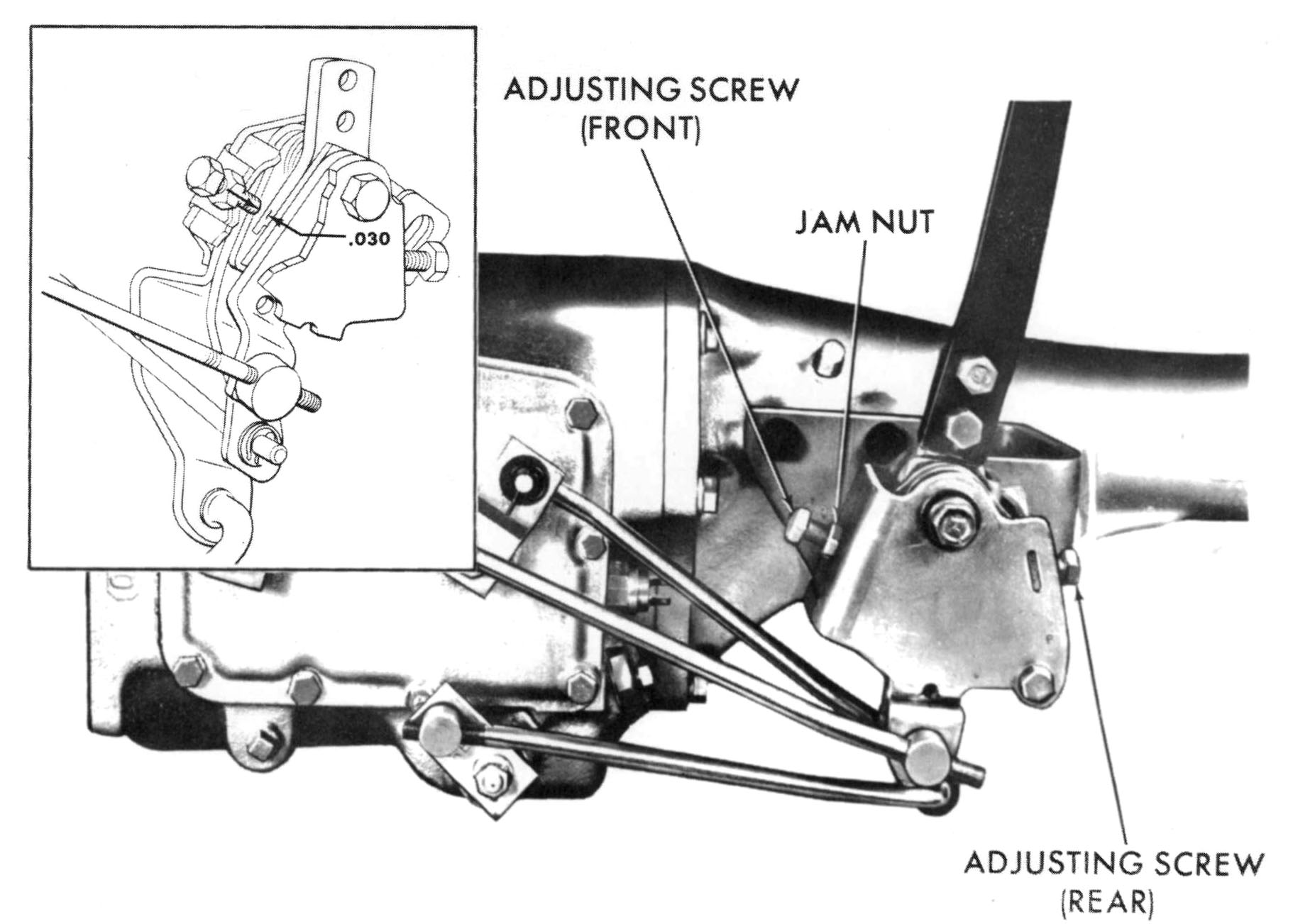
STUB LEVER STOP ADJUSTMENT
To avoid overloading the transmission and shift linkage on all models except Valiant and Dart, adjustable stop screws limit travel of the stub lever in the selector mechanism. To adjust the stops, proceed as follows:
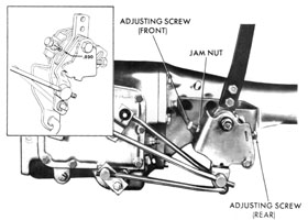
- Loosen the jam nuts on the front and rear stop screws and back the screws out two or three turns.
- With the control lever and transmission in fourth speed position, insert a .030 inch feeler gauge between the front of the stub lever and the end of the front adjustment screw. Turn the screw in until the clearance between the screw and the stub lever is .030" (See insert in Frame 20), and tighten the jam nut.
- With the control lever in third speed position, repeat this procedure to establish .030" clearance between the rear edge of the stub lever and the end of the rear adjustment screw.
|
|