
Imperial Home Page -> Literature -> Articles -> New Features for 1964 -> Steering & Suspension
|
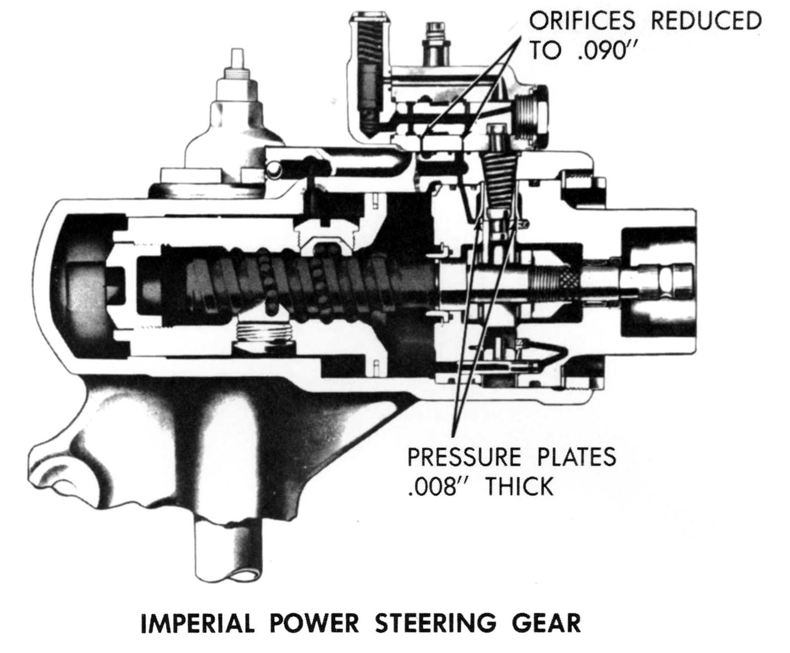
IMPERIAL STEERING GEAR INTERNAL CHANGES
|
|
|
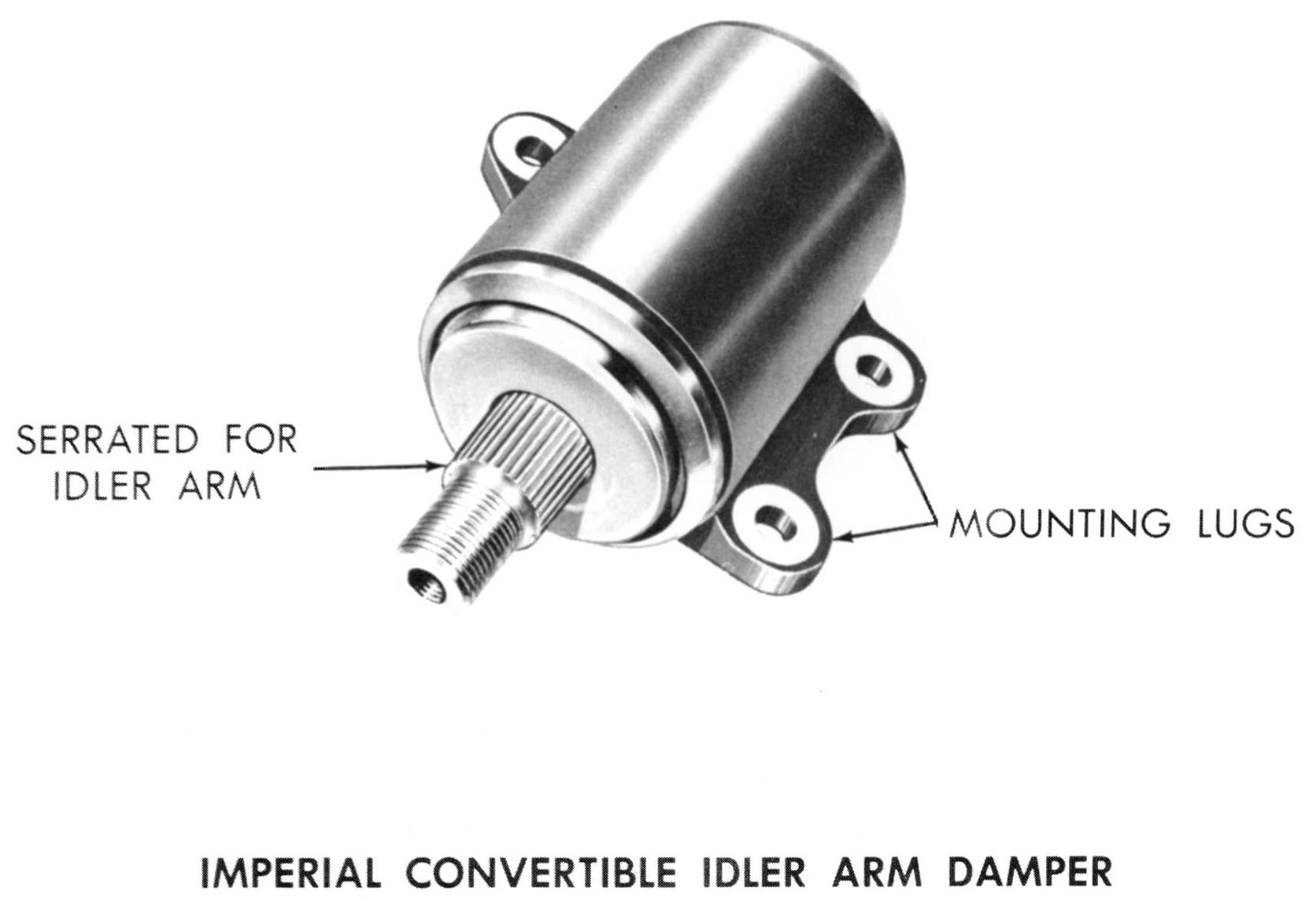
IMPERIAL CONVERTIBLE IDLER ARM DAMPER
|
|
|
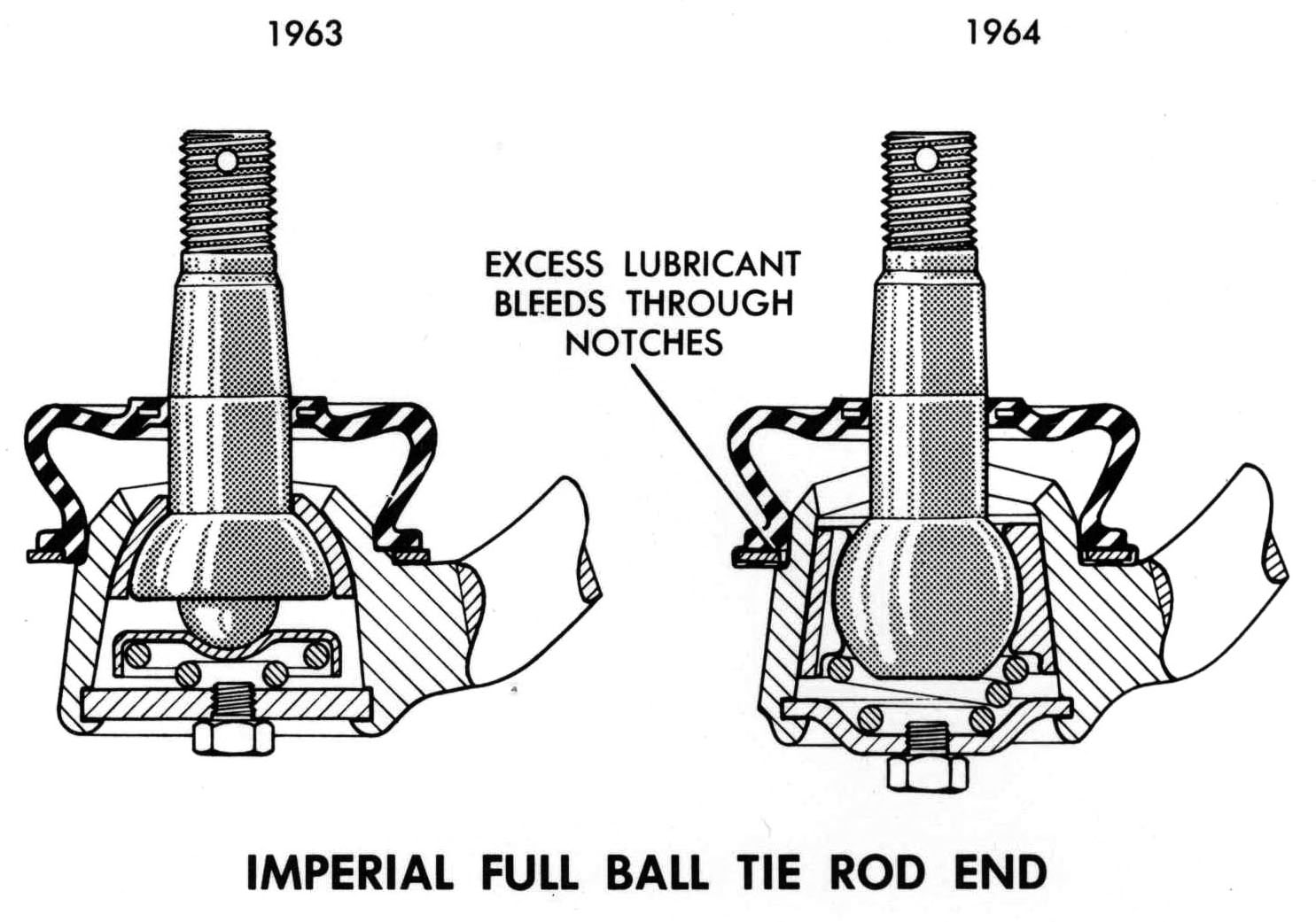
IMPERIAL FULL BALL TIE ROD ENDS
|
|
|
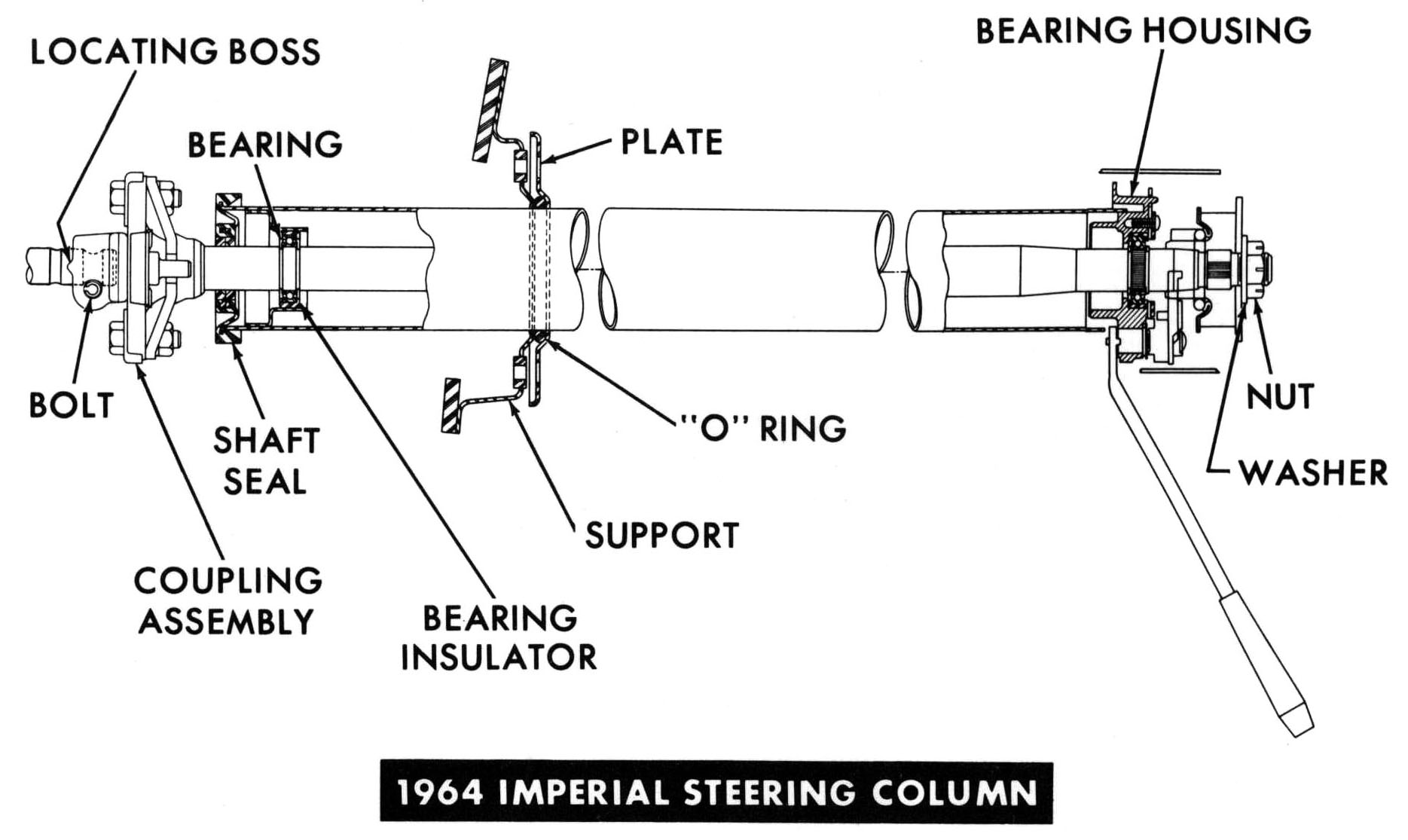
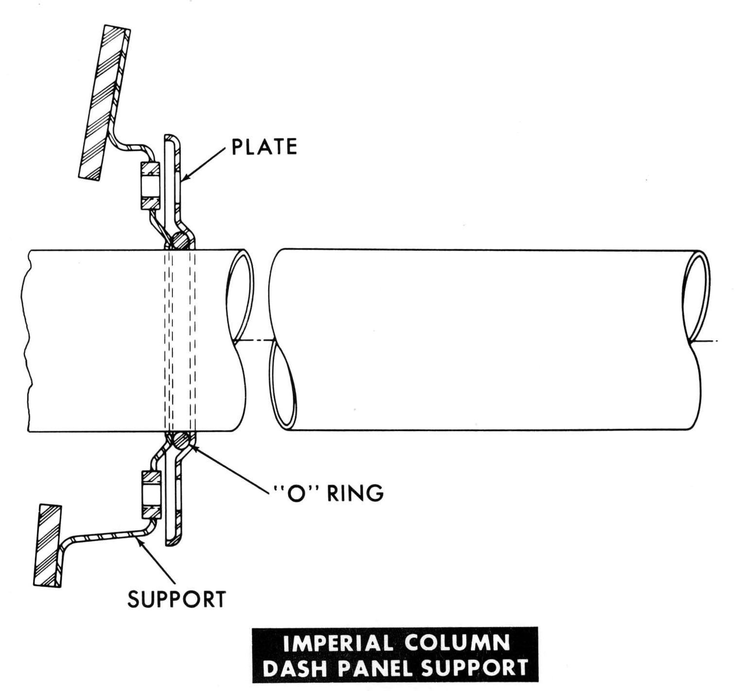
IMPERIAL STEERING COLUMN WITH LOWER BEARING
|
|
|
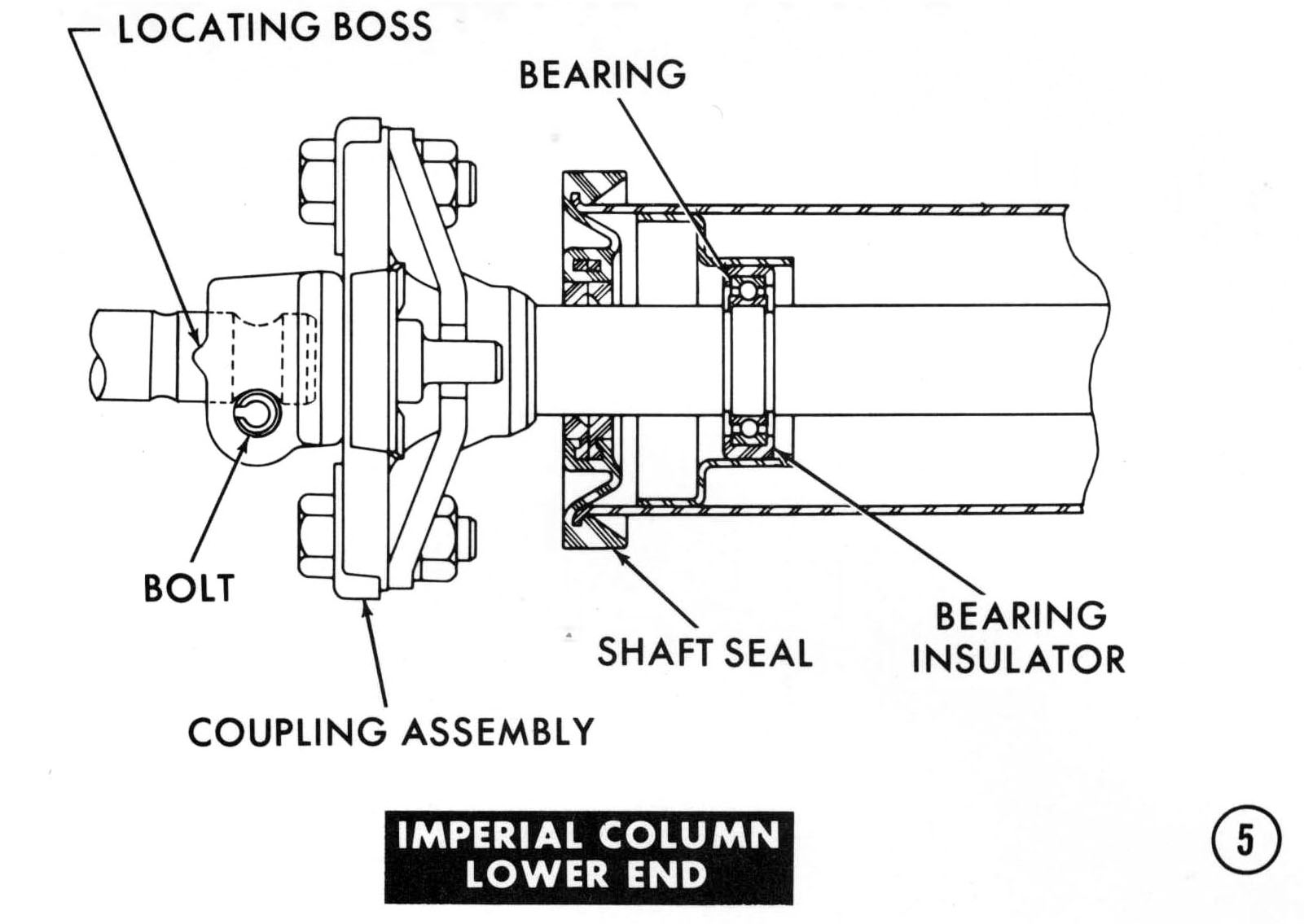
IMPERIAL COLUMN - LOWER END
|
|
|
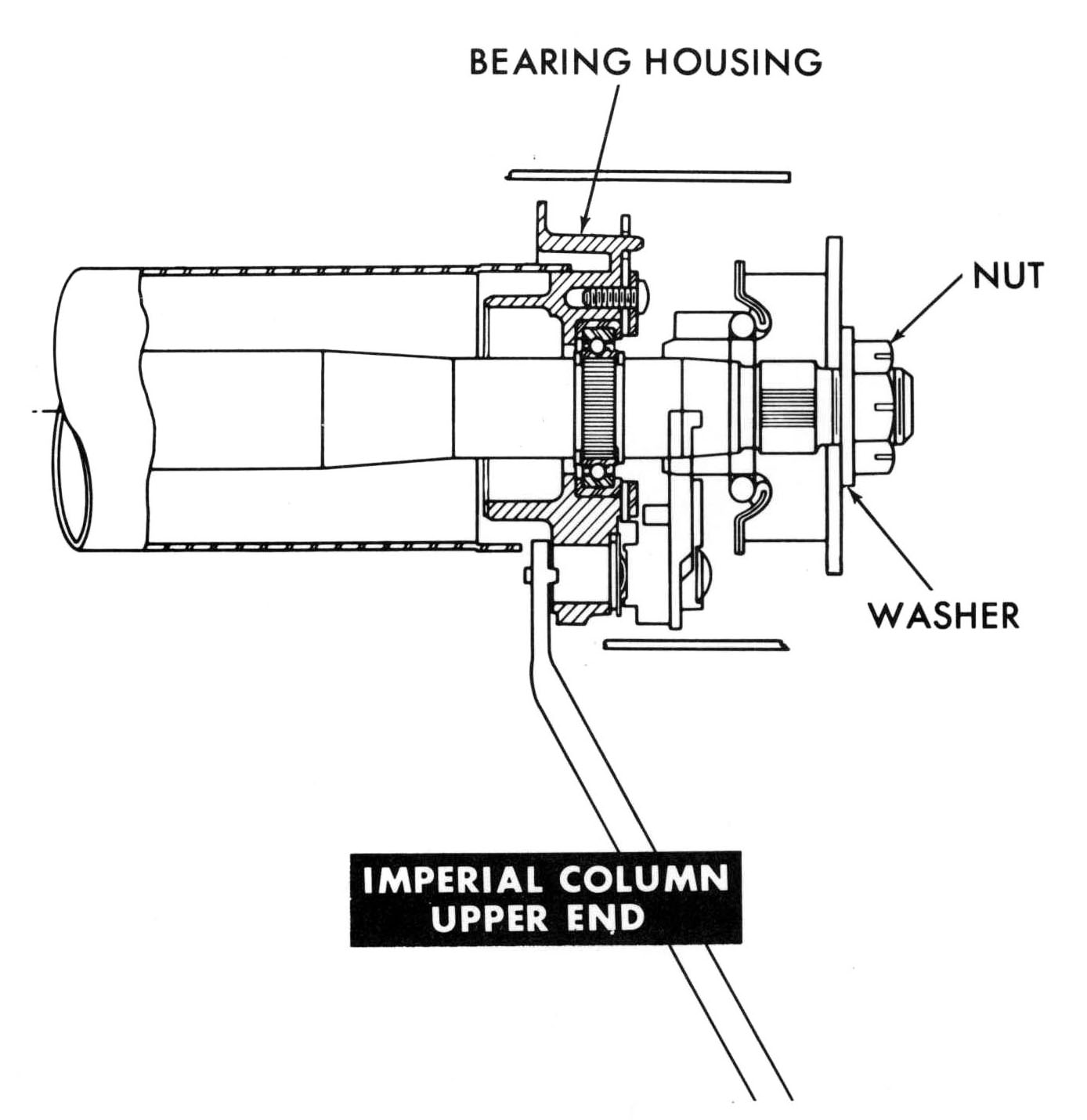
IMPERIAL COLUMN UPPER END
|
|
|
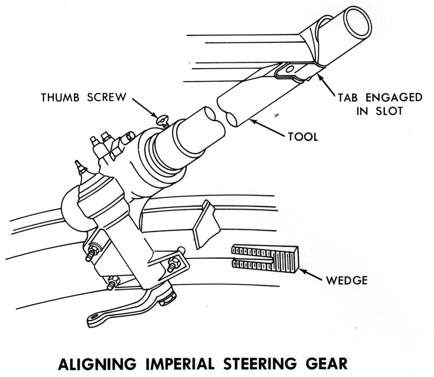
IMPERIAL GEAR AND COLUMN ALIGNMENT AND COLUMN INSTALLATION
|
|
|
|
|
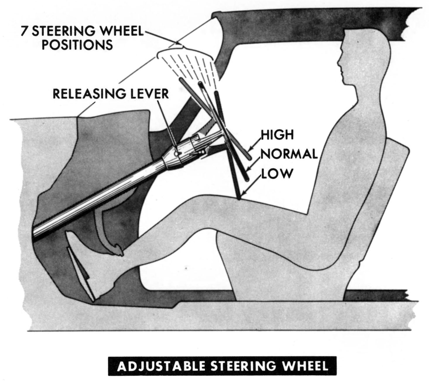
STEERING COLUMN WITh TILT WHEEL
|
|
|
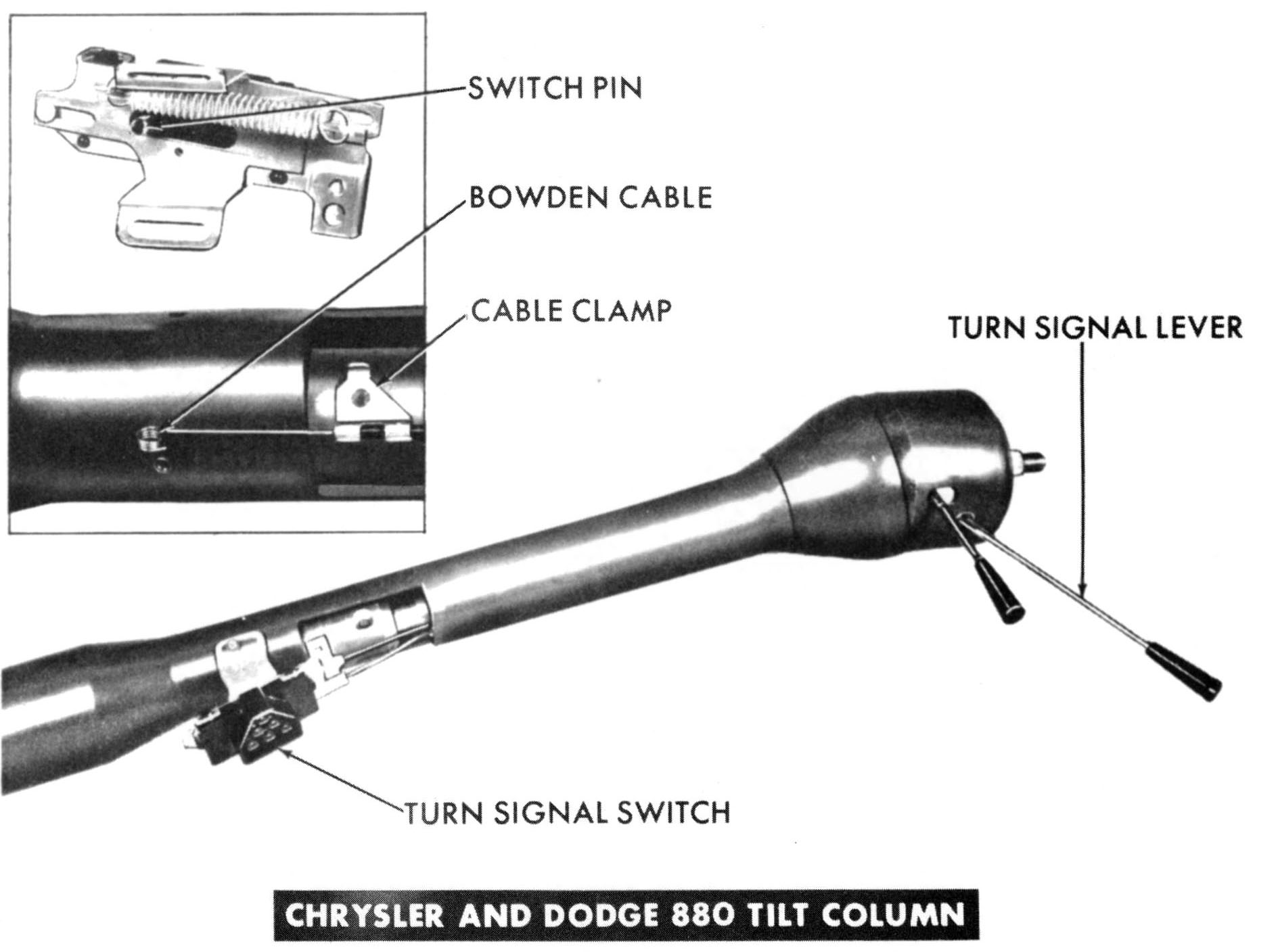
REMOVAL AND INSTALLATION OF TURN SIGNAL SWITCH
|
|
|
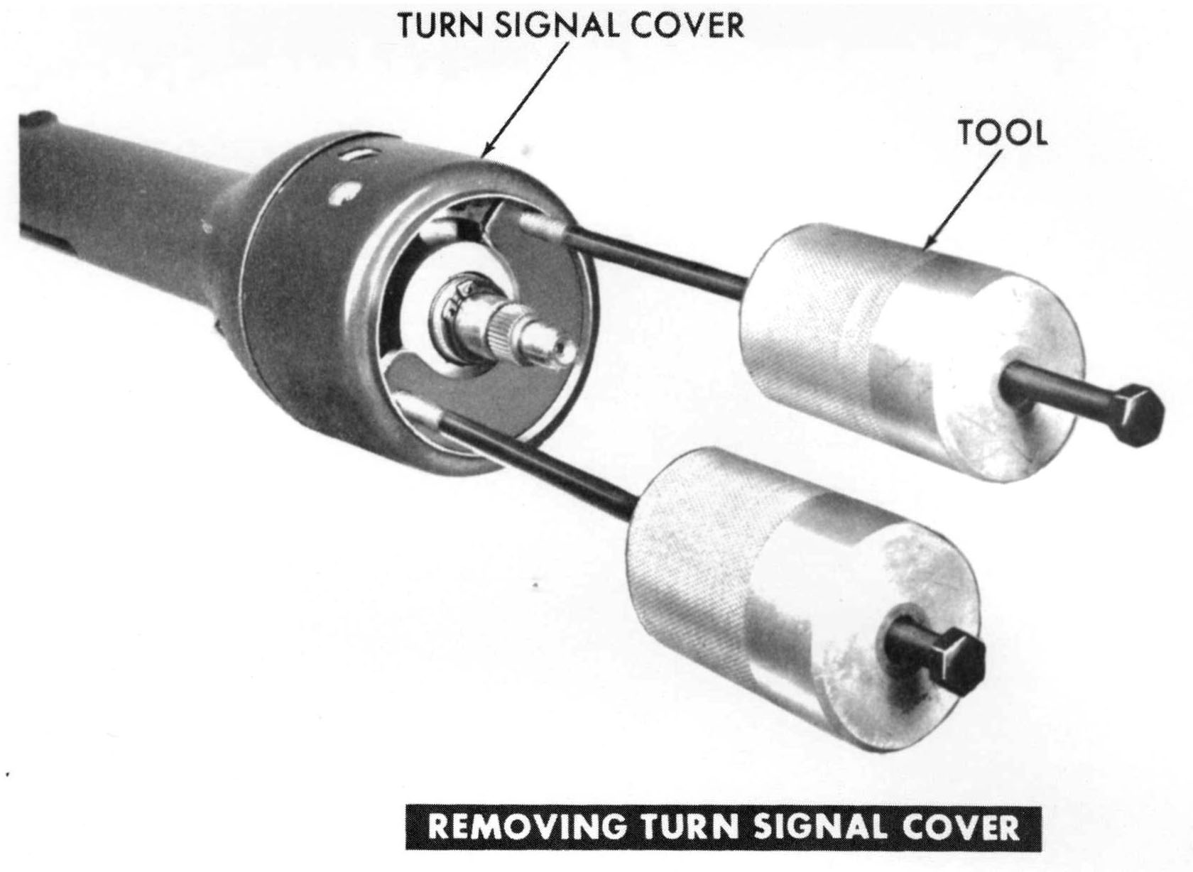
REMOVE TURN SIGNAL COVER
|
|
|
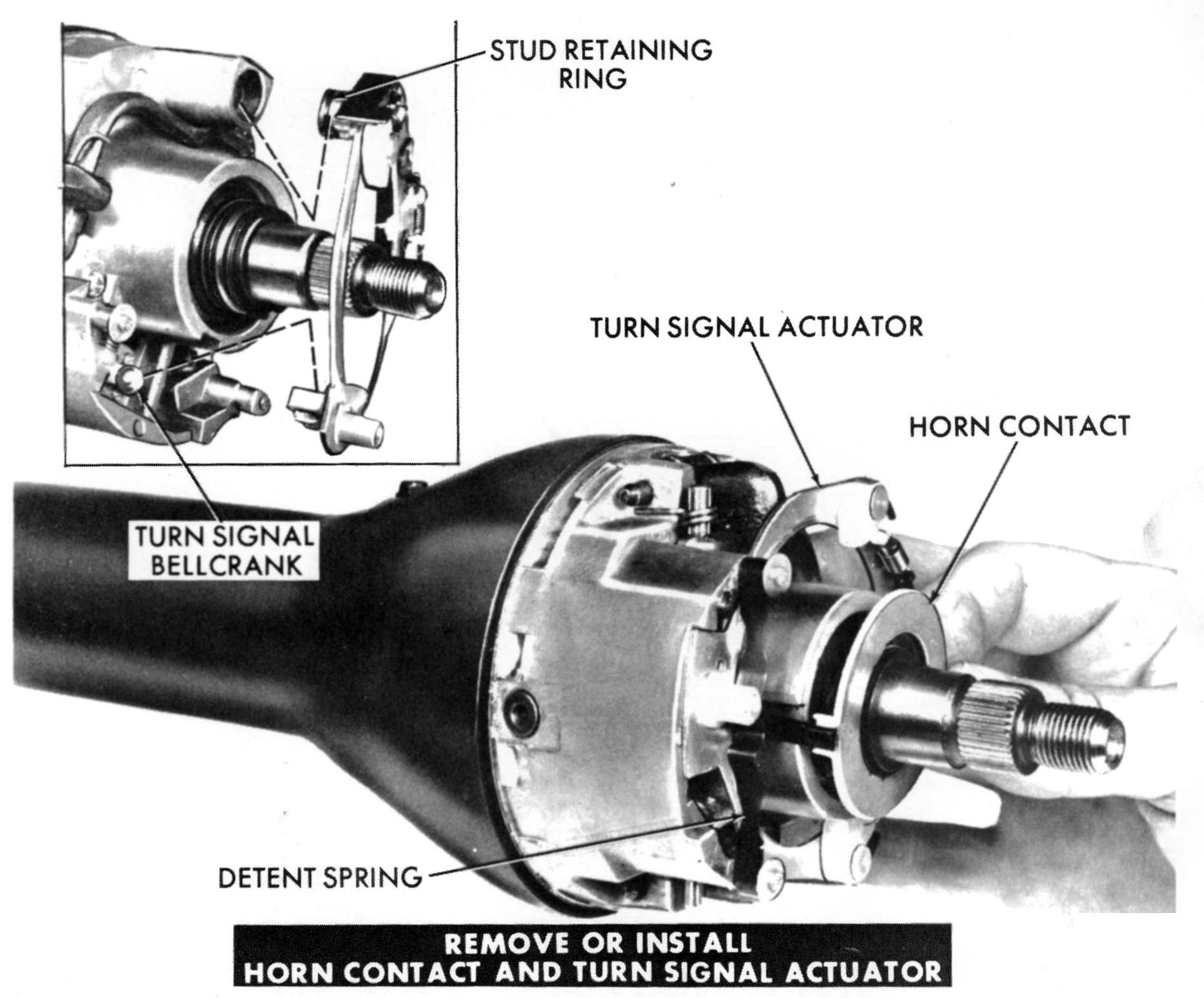
REMOVE OR INSTALL HORN CONTACT AND TURN SIGNAL YOKE
|
|
|
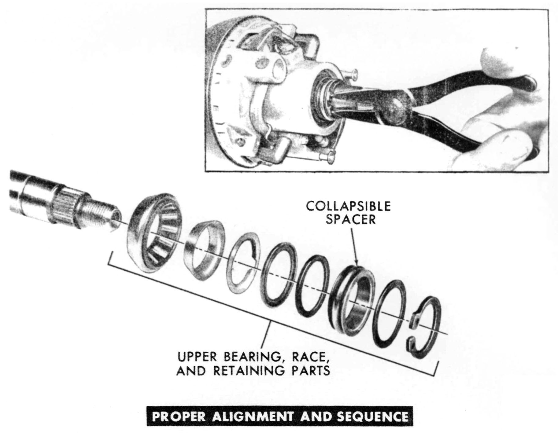
UPPER BEARING AND RELATED PARTS
|
|
|
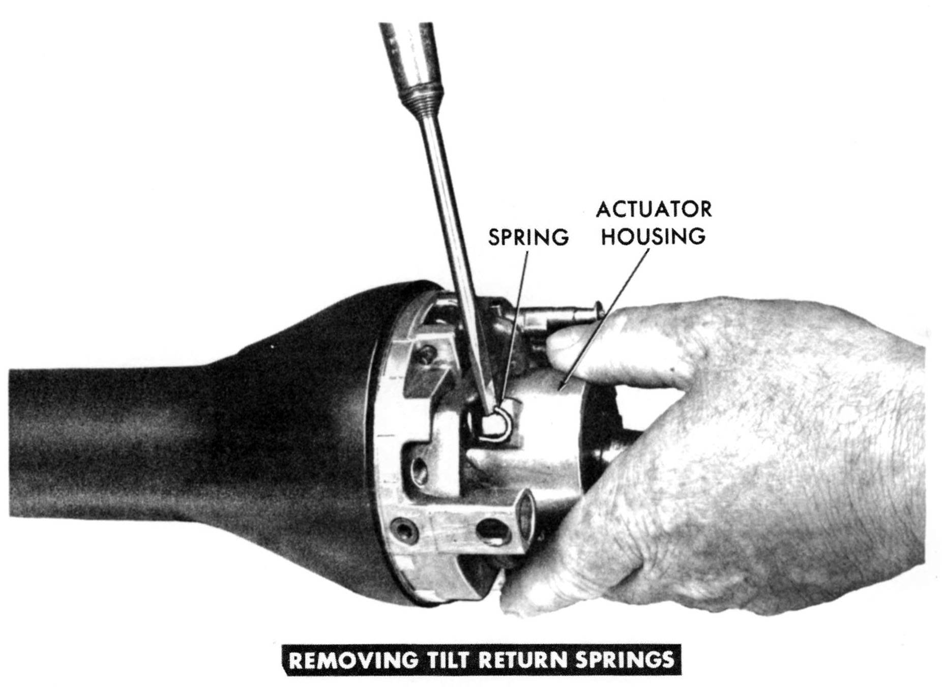
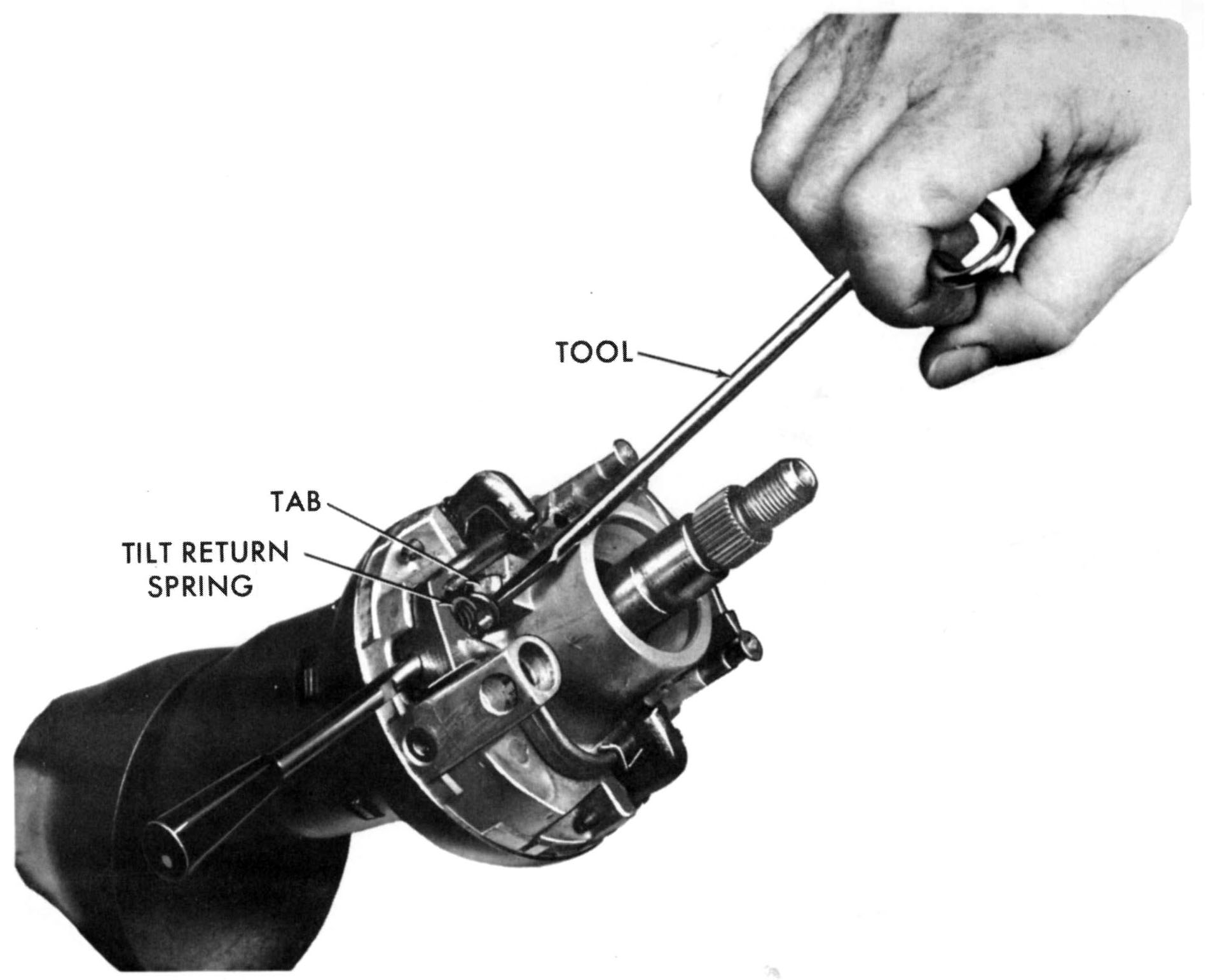
UNHOOK TILT RETURN SPRINGS
|
|
|
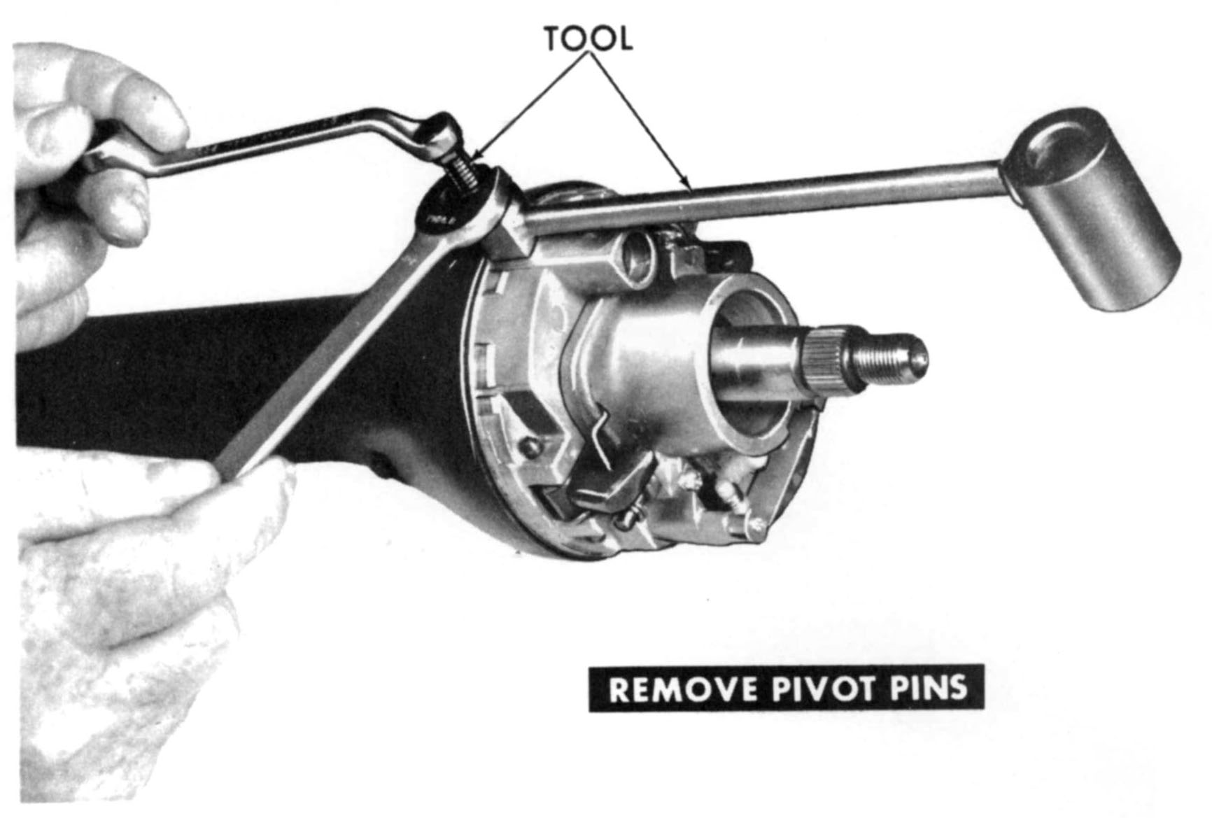
REMOVE ACTUATOR HOUSING PIVOT PINS
|
|
|
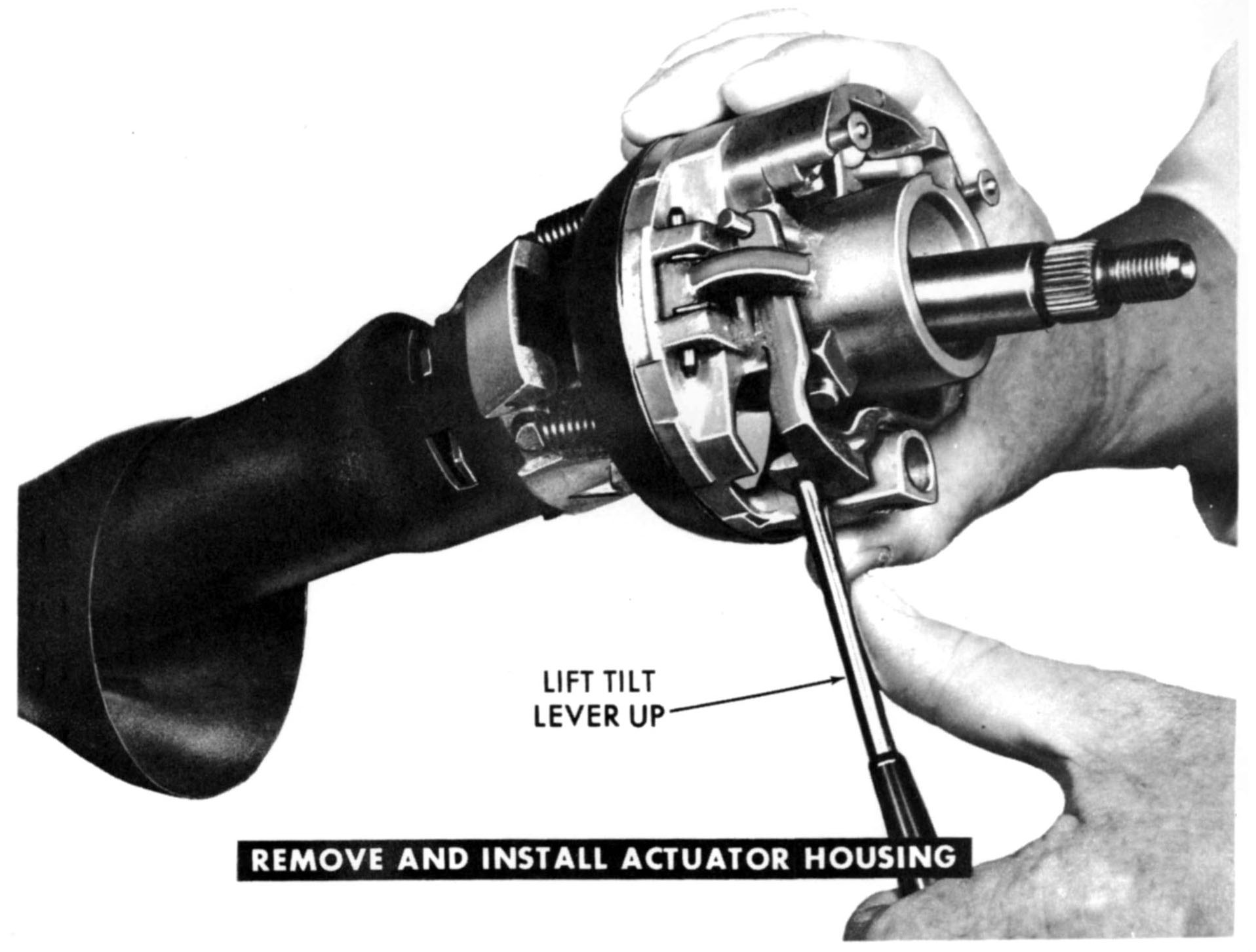
REMOVE OR INSTALL ACTUATOR
|
|
|
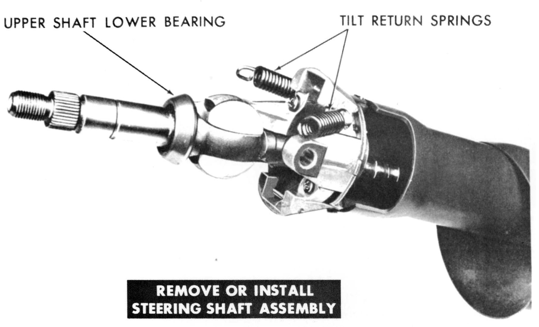
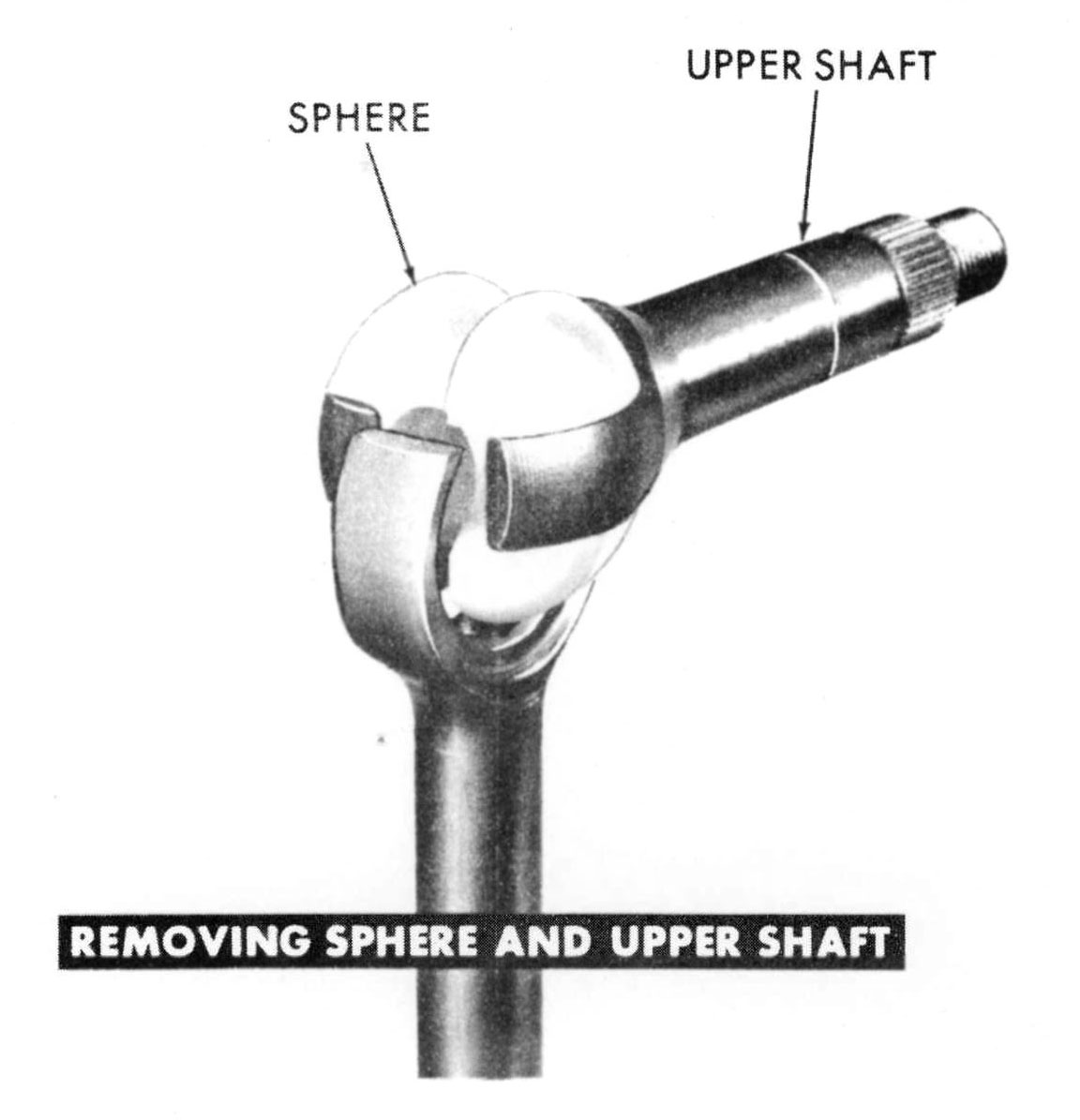
REMOVE OR INSTALL STEERING SHAFT
|
|
|
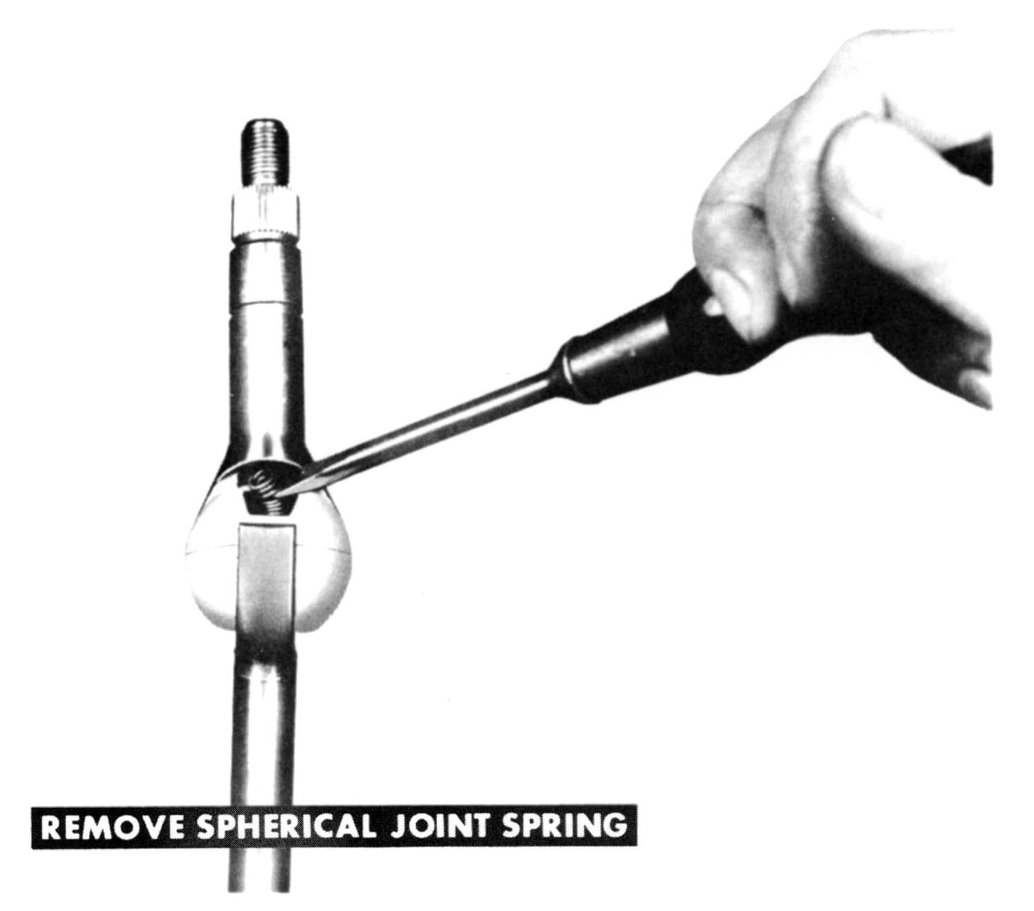
REMOVE OR INSTALL SPRING FROM SPHERICAL BEARING
|
|
|
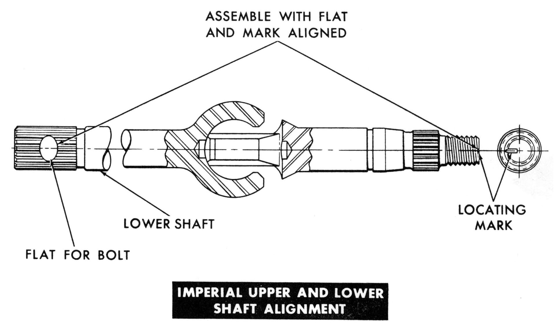
DISASSEMBLE OR ASSEMBLE STEERING SHAFT
|
|
|
ALIGN SPLINES WHEN ASSEMBLING
|
|
|
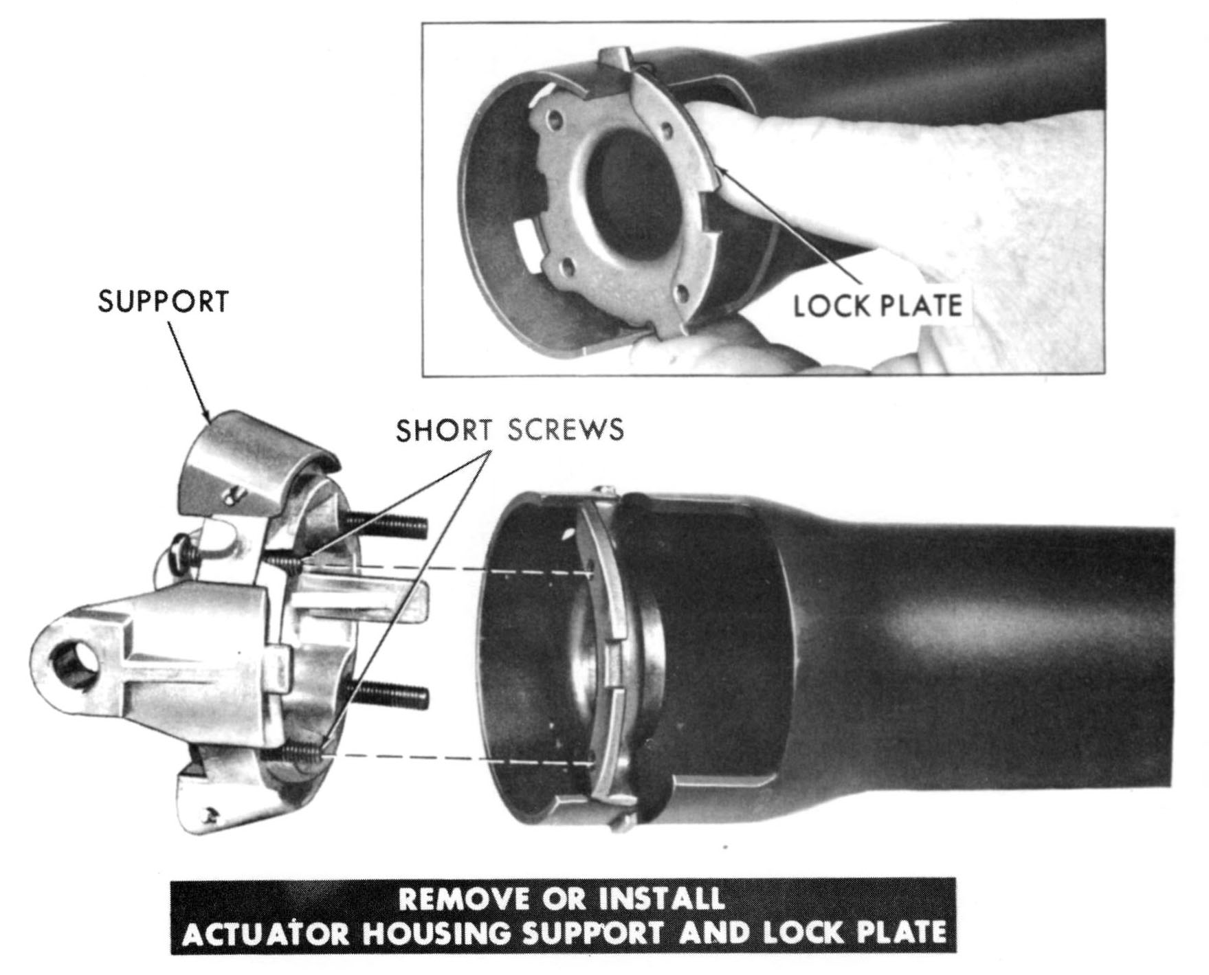
REMOVE OR INSTALL ACTUATOR HOUSING SUPPORT AND LOCK PLATE
|
|
|
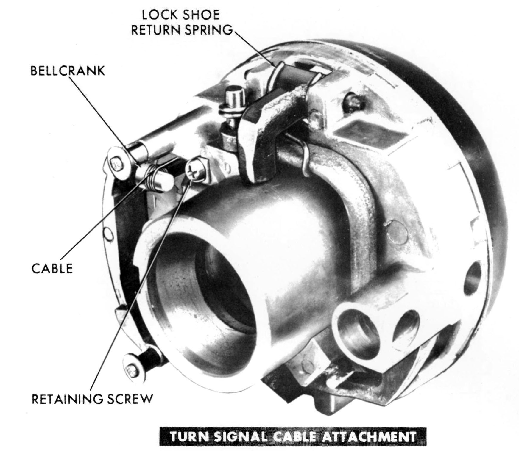
REMOVE OR INSTALL TURN SIGNAL SWITCH CONTROL CABLE
|
|
|
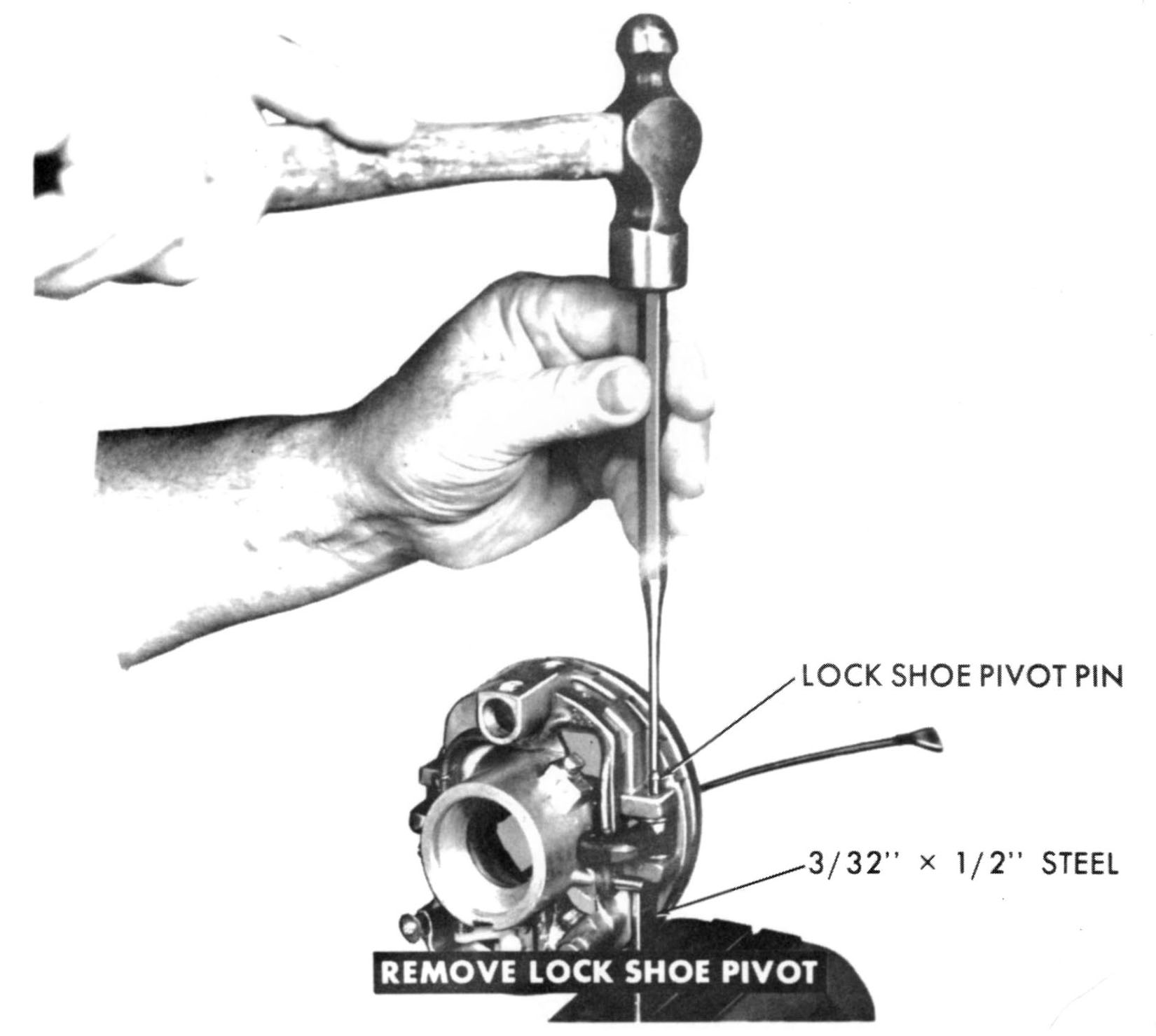
REMOVE OR INSTALL LOCK SHOE PIVOT PINS
|
|
|
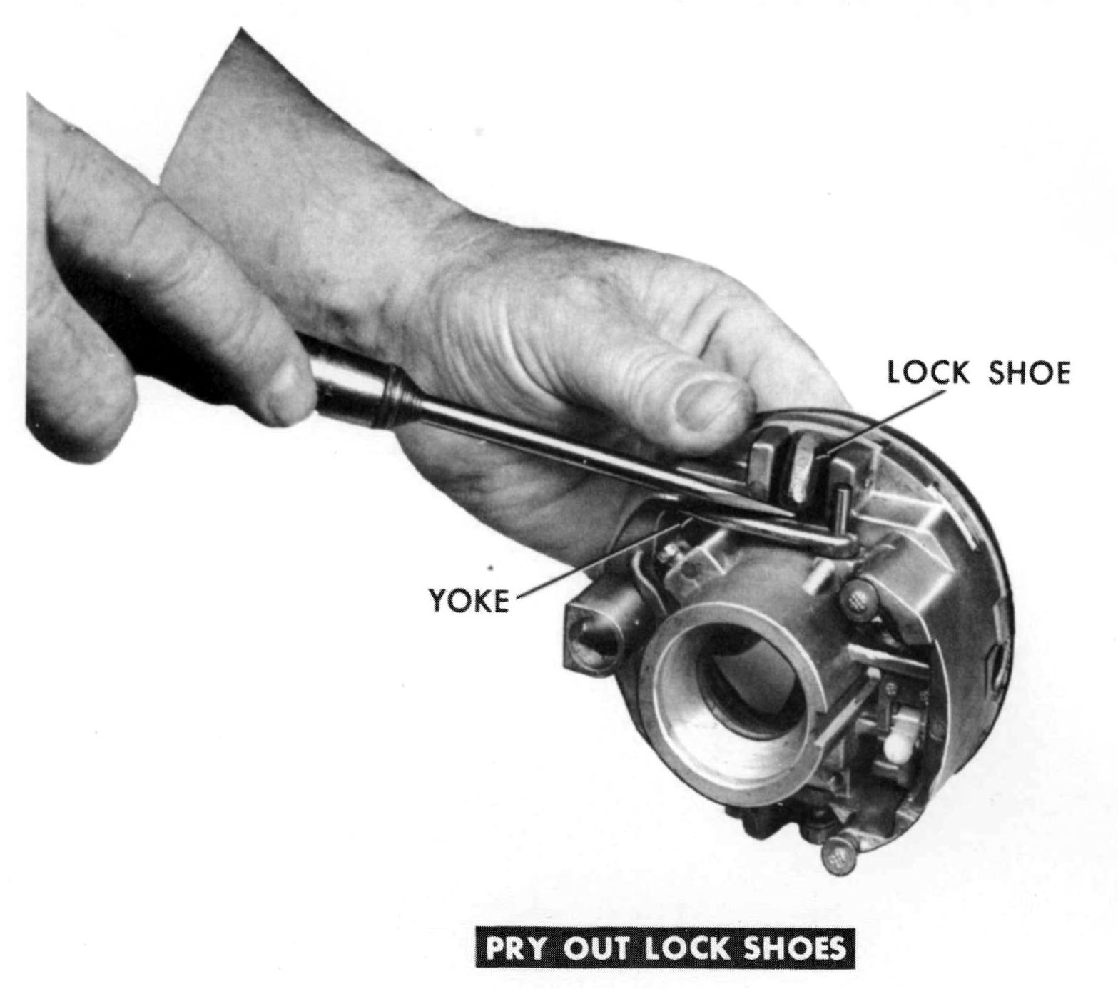
REMOVE OR INSTALL LOCK SHOES
|
|
|
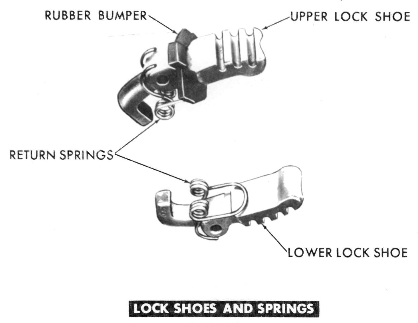
UPPER AND LOWER LOCK SHOES
|
|
|
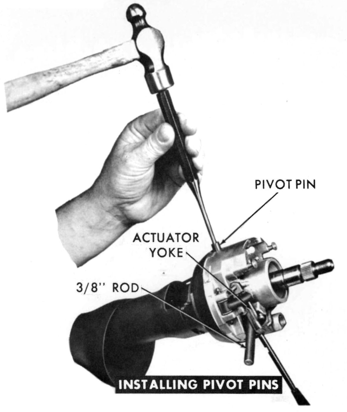
INSTALL ACTUATOR PIVOT PINS
|
|
|
HOOK TILT RETURN SPRINGS OVER TABS
|
|
|
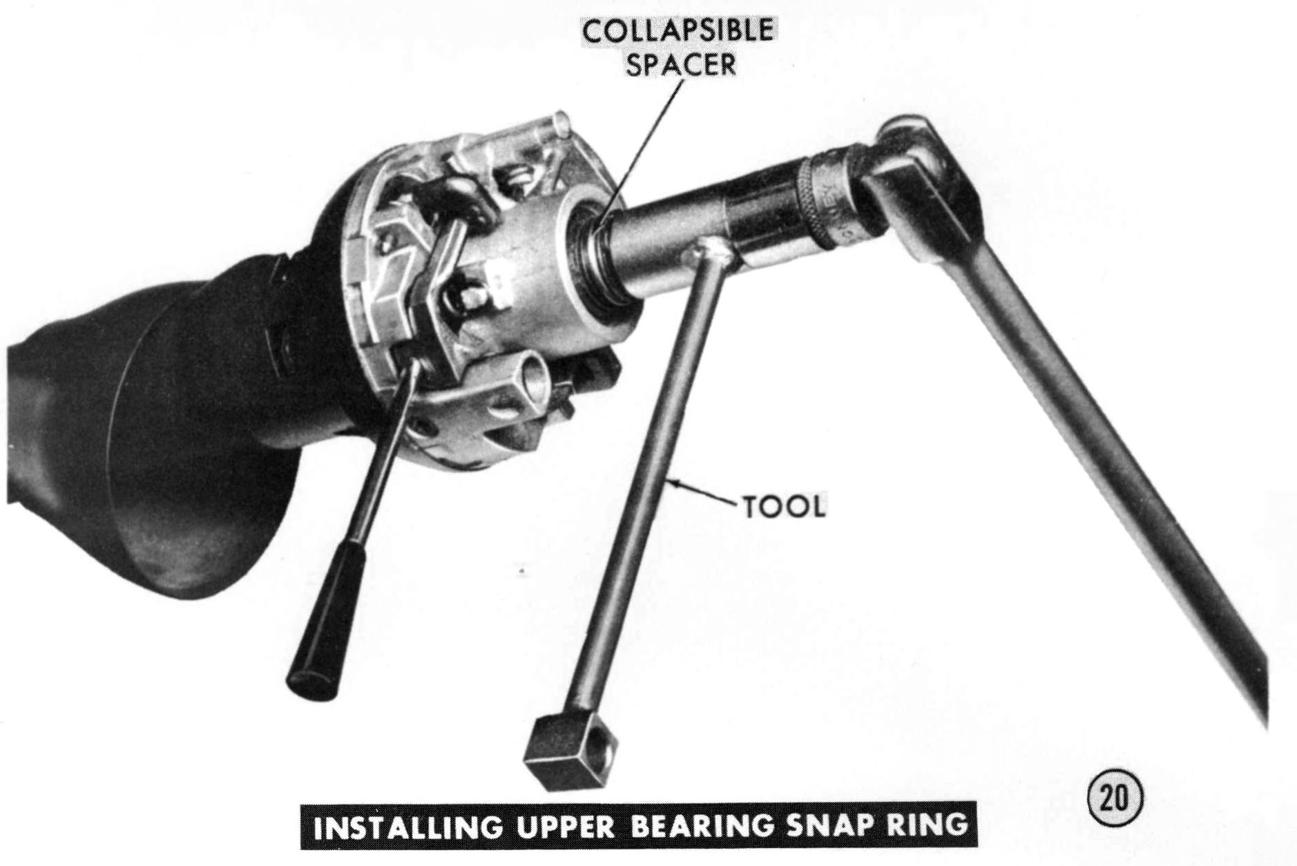
INSTALL UPPER BEARING AND RELATED PARTS
|
|
|
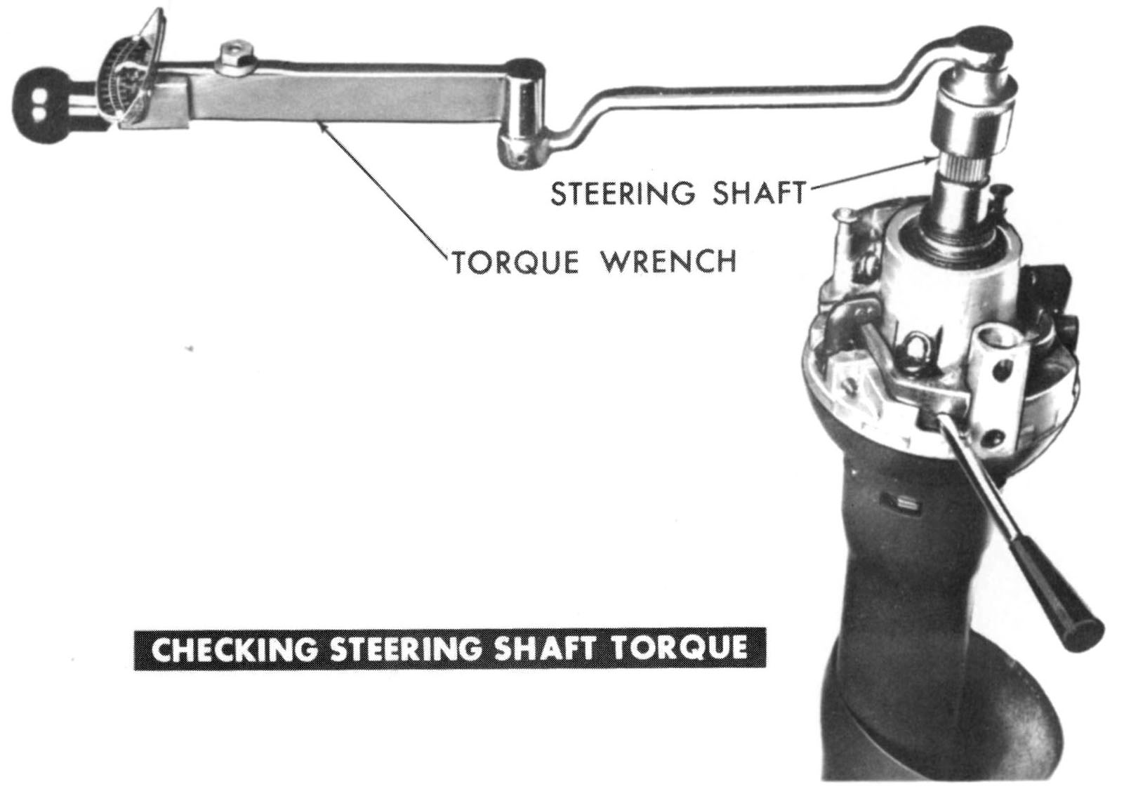
CHECK SHAFT ROTATING TORQUE
|
|
|
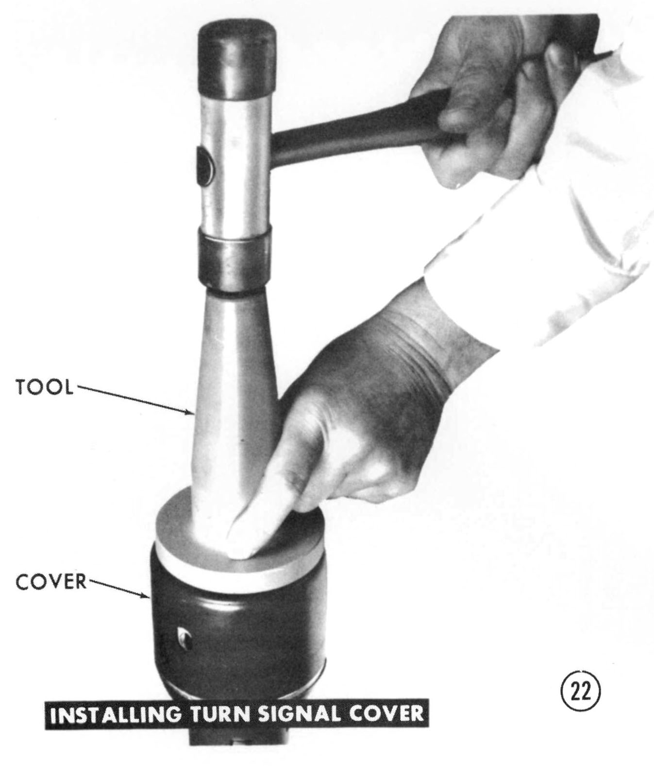
INSTALL TURN SIGNAL COVER
|
|
|
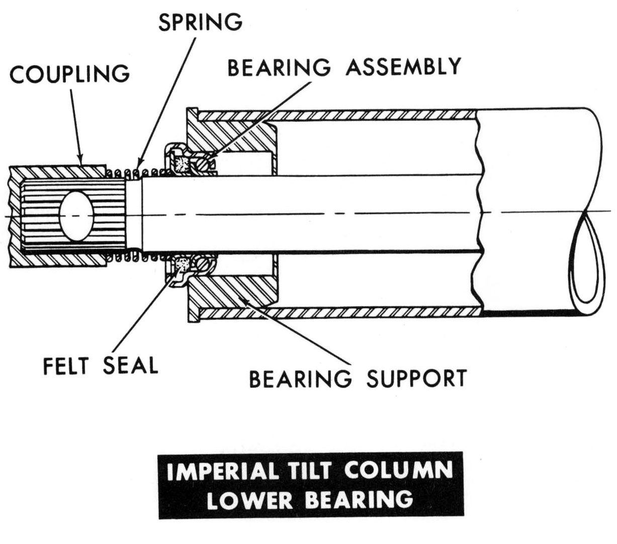
LOWER SHAFT BEARING - IMPERIAL ONLY
|
|
|
|
|
Having trouble with printouts coming out way too small, or pieces of a document printing acro ss sev eral page s? Then go to our "How To Print Imperial Literature" page to learn how to print an item at the size you'd like. |
This page was last updated 13 January 2010. Send us your feedback, and come join the Imperial Mailing List - Online Car Club
