
Imperial Home Page -> Literature -> Articles -> New Features for 1964 -> Torqueflite Design Changes
|
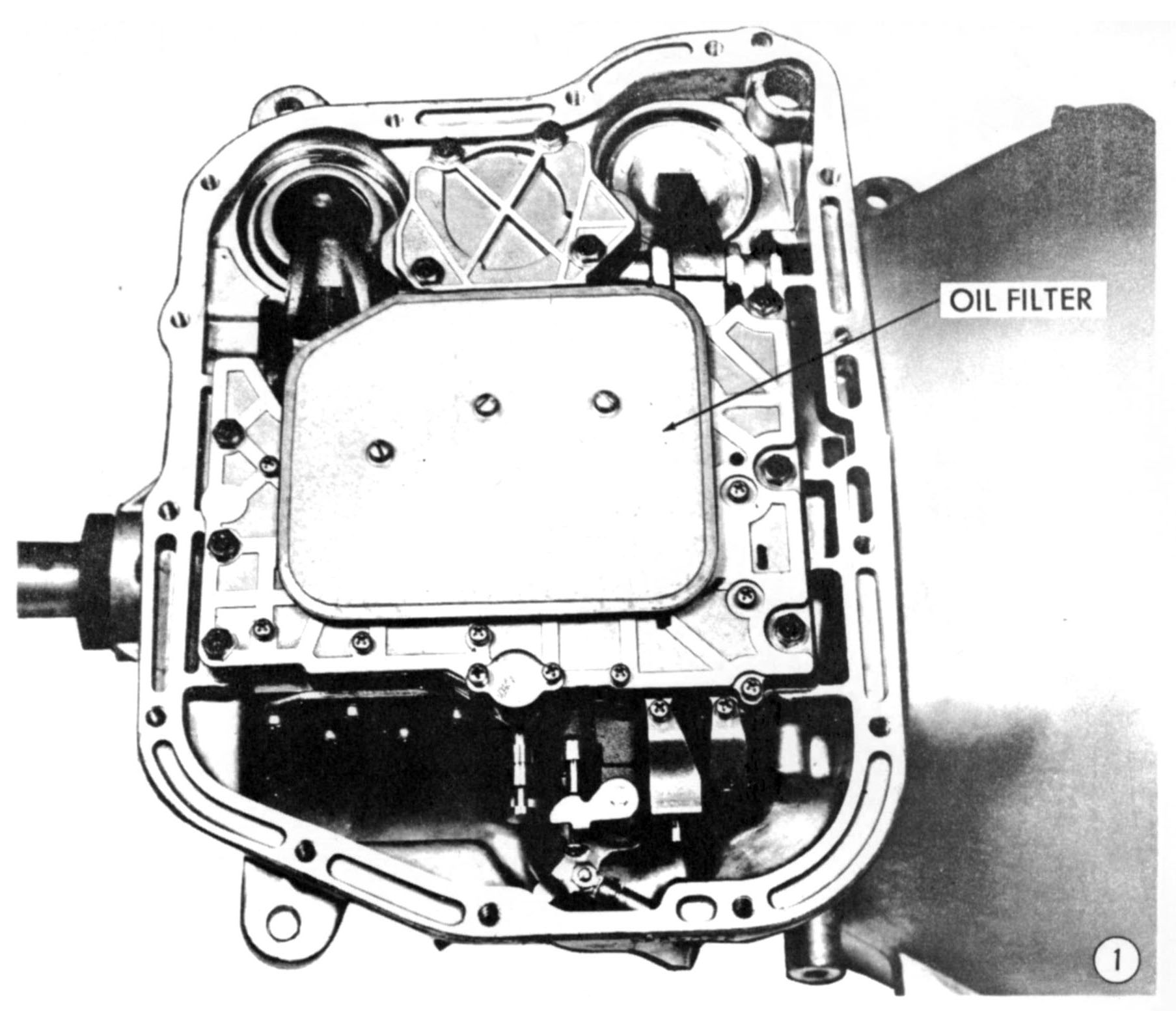
OIL FILTER All 1964 model torqueflites, both for 6-cylinder and 8- cylinder engines, have a new internal oil filter. The oil screen assembly has been redesigned to contain a sheet of Dacron felt, over two layers of perforated steel. The filter assembly is installed on the transfer plate with three slotted head screws, in the same manner as the previous screen assembly. This change necessitated no change in the valve body or in the transfer plate. The new filter is thicker than the screen assembly it replaces, so a well is stamped in the oil pan to, compensate for the increased thickness. The factory fill of oil, and the filter, should be good for the life of the vehicle in normal operation. In heavy duty operation at 32,000-mile intervals, and in extreme heavy duty operations at 10,000-mile intervals the fluid and the filter should be replaced. Diagnosis - If the filter becomes clogged, the condition will first become evident in excessive delay in obtaining reverse drive. Some delay is normal when the oil is cold, but when the transmission is warmed up to normal operating temperature, there should be no noticeable delay in obtaining reverse. This filter will do a more thorough job of excluding particles from the transmission hydraulic circuits than the previous filter, because both the front and rear pumps draw through the filter, whereas only the oil passing through the torque converter was filtered by the "T" Series, external, filter. Elimination of the external filter also eliminates two potential leak points - the tubing connections at the filter. |
|
|
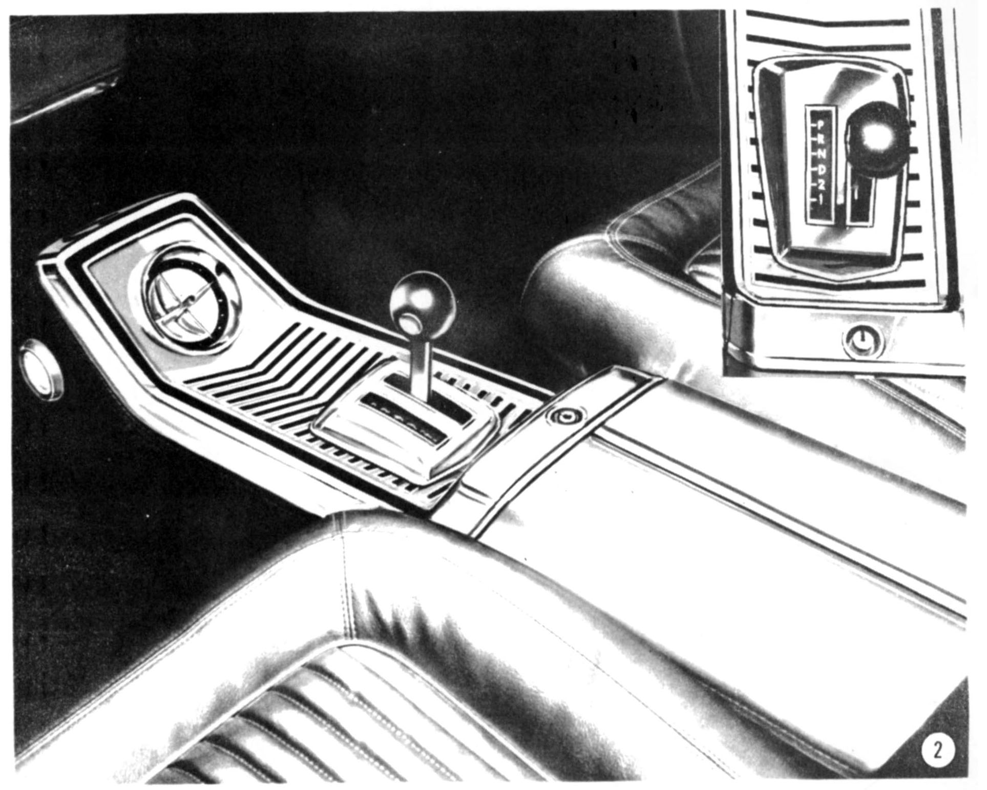
TORQUEFLITE CONSOLE SHIFT All Chrysler, Dodge, and Plymouth Console Models, whether equipped with automatic or manual transmissions, have gearshift selector levers on the console. The A-727 torqueflite shift lever, in console models, extends through a fore-and-aft slot in the console and is spring loaded to the right against a series of gates. There are six selective positions, reading from rear to front - Low (1), Second (2), Drive Cd), Neutral (N), Reverse (R), and Park (P). |
|
|
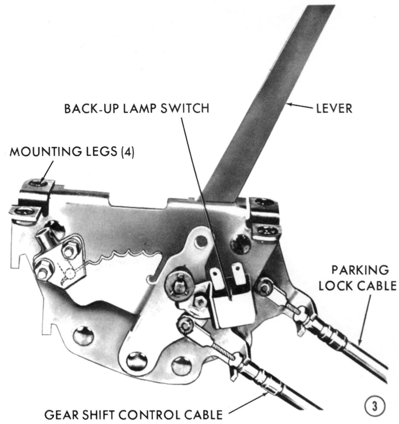
In addition to the gating provided along the top of the lever bracket, each of the six positions is detented. The back-up light switch is mounted on the cable operating lever and is actuated by a hump on the side plate when the shift lever is moved into reverse. |
|
|
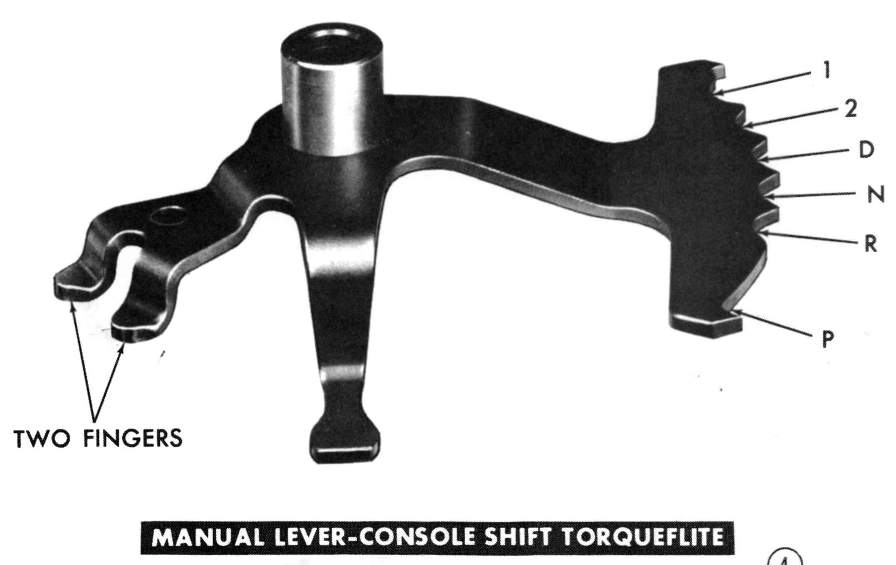
The valve body is modified, mostly in the area of the manual valve and the manual valve operating lever. The valve, and its pressure passages in the valve body, has been modified to provide for the sixth (Park) selection. The manual valve operating lever has six rather than five detents in its "Rooster Comb". It also has two "Fingers" so that the neutral safety switch is grounded in either "Neutral" or "Park" position. |
|
|
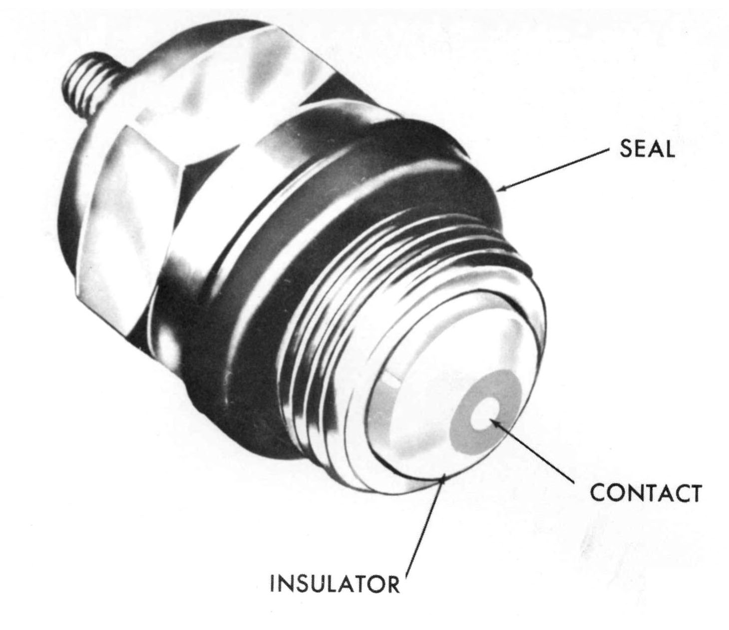
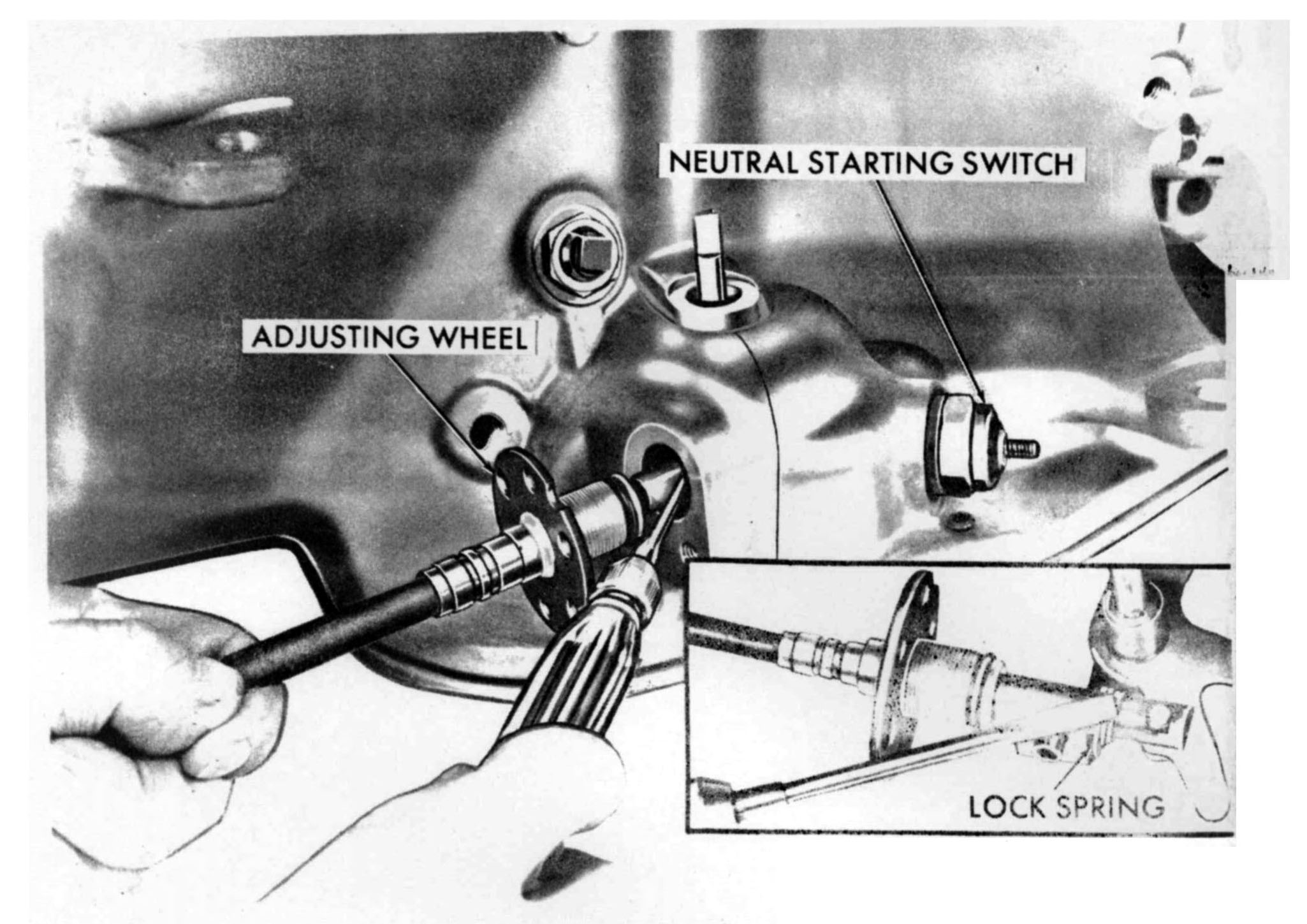
The neutral safety switch in Console A-727 TorqueFlites is in the same location as in other TorqueFlites, but is of a new design. It has a larger spring loaded nylon insulator plug with a pin-like metal contact in its center. The manual valve operating lever must be precisely in Neutral or Park position before the starter circuit can be energized. As a matter of fact, difficulty can be encountered when reinstalling a valve body in getting it aligned with the switch. Before tightening the ten valve body retaining bolts, check to make sure that a �Finger� of the manual valve lever centers on the switch contact in "Neutral" or "Park". The switch seal is a special design, unlike the cupped washer and 0-ring seal used on other models. This is a one�piece seal, consisting of a cupped aluminum washer entirely coated with Butyl rubber. The switch and seal are installed by merely positioning the seal on the switch and threading the switch into the transmission case, tightening to 20-30 foot-pounds. There is no adjustment other than observing the 20-30 foot-pound specification. |
|
|
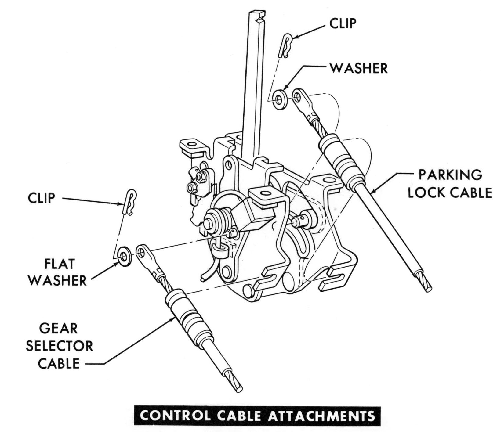
CONTROL CABLE ADJUSTMENTS GEAR SELECTOR CABLE ADJUSTMENT The gear selector cable is attached to the selector lever in much the same manner as with a push button box, with a cable eye over a pin, secured by a flat washer and spring clip. |
|
|
The removal and installation procedures for the gear selector cable at the transmission are the same as those followed with push button cables, but the adjustment procedure is different. To make this adjustment, proceed as follows:
|
|
|
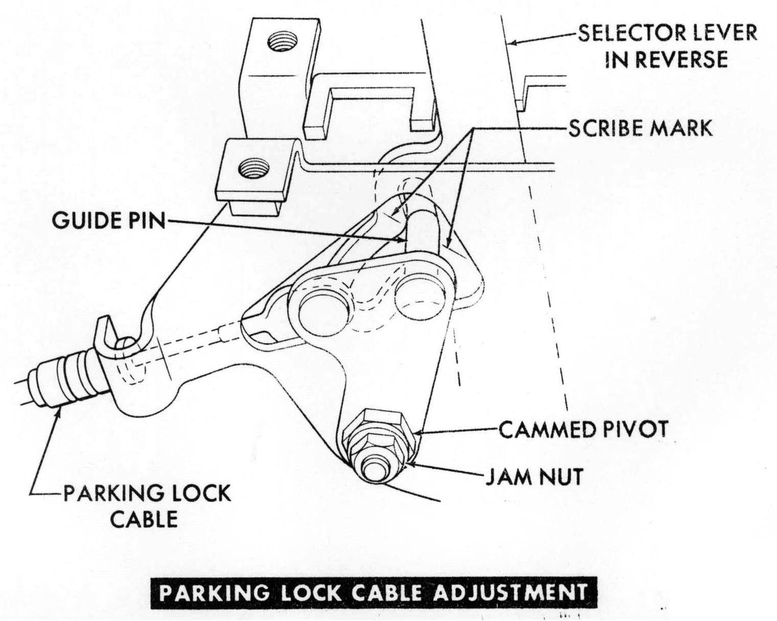
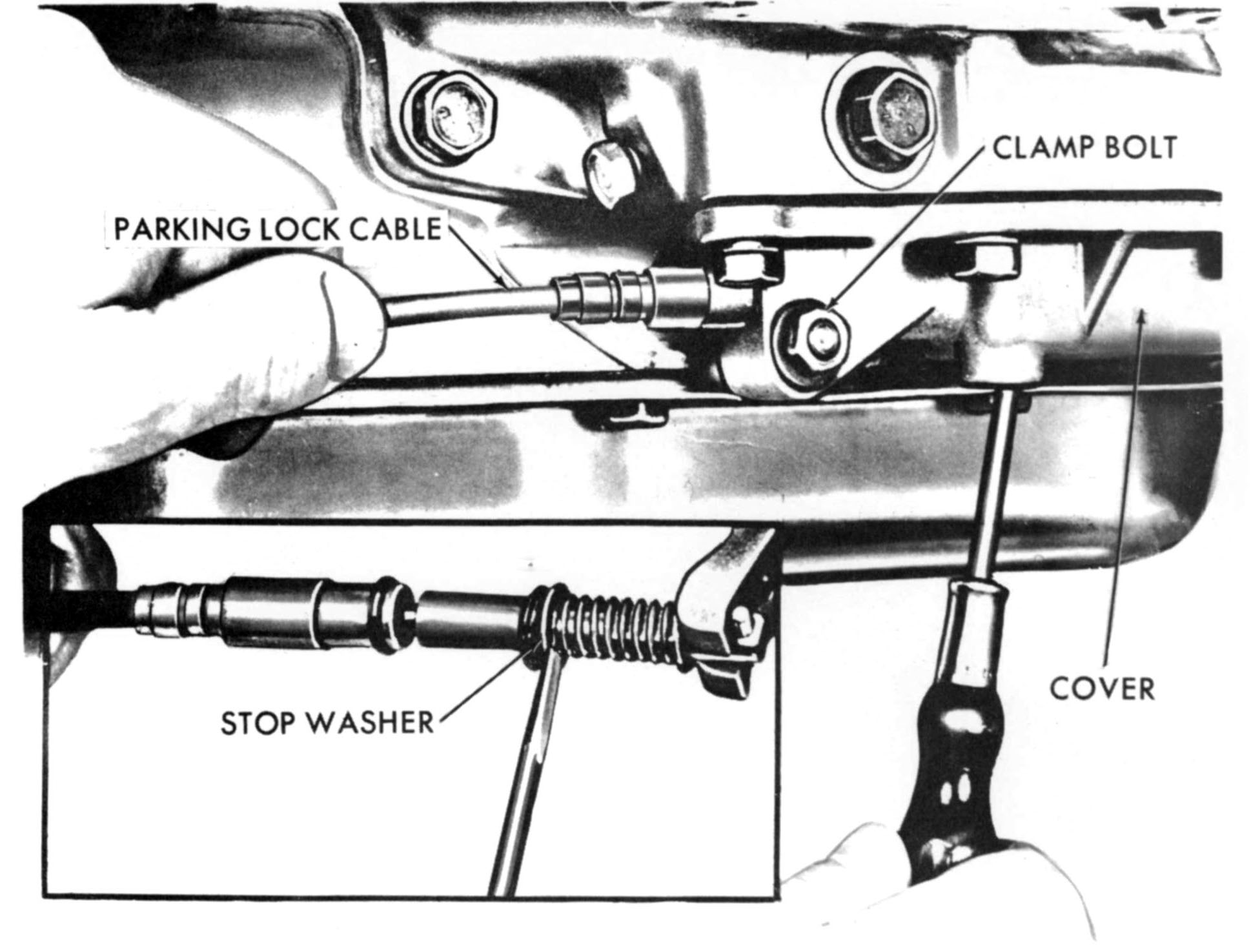
PARKING LOCK CABLE (SELECTOR LEVER END) The parking lock cable operating lever on the selector lever assembly rotates on a cammed pivot similar to the one on a push button box. The position of the parking lock cable operating lever is adjusted, as part of the assembly procedure for the selector lever mechanism, to establish the correct amount of parking lock cable travel. To make this adjustment, proceed as follows:
|
|
|
PARKING LOCK CABLE (TRANSMISSION END) The procedures for parking lock cable removal, installation, and adjustment at the transmission end are the same as for conventional TorqueFlites. |
|
|
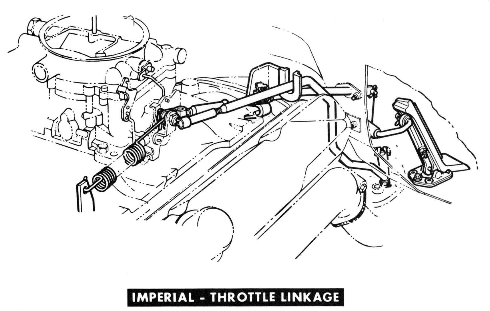
THROTTLE LINKAGES With the exception of Imperial Models, all 1963 throttle linkage systems are carried over into 1964. A cable throttle linkage will be used in Imperial, similar to the Plymouth & Dodge V-8 throttle linkage, and adjusted in the same manner. |
|
|
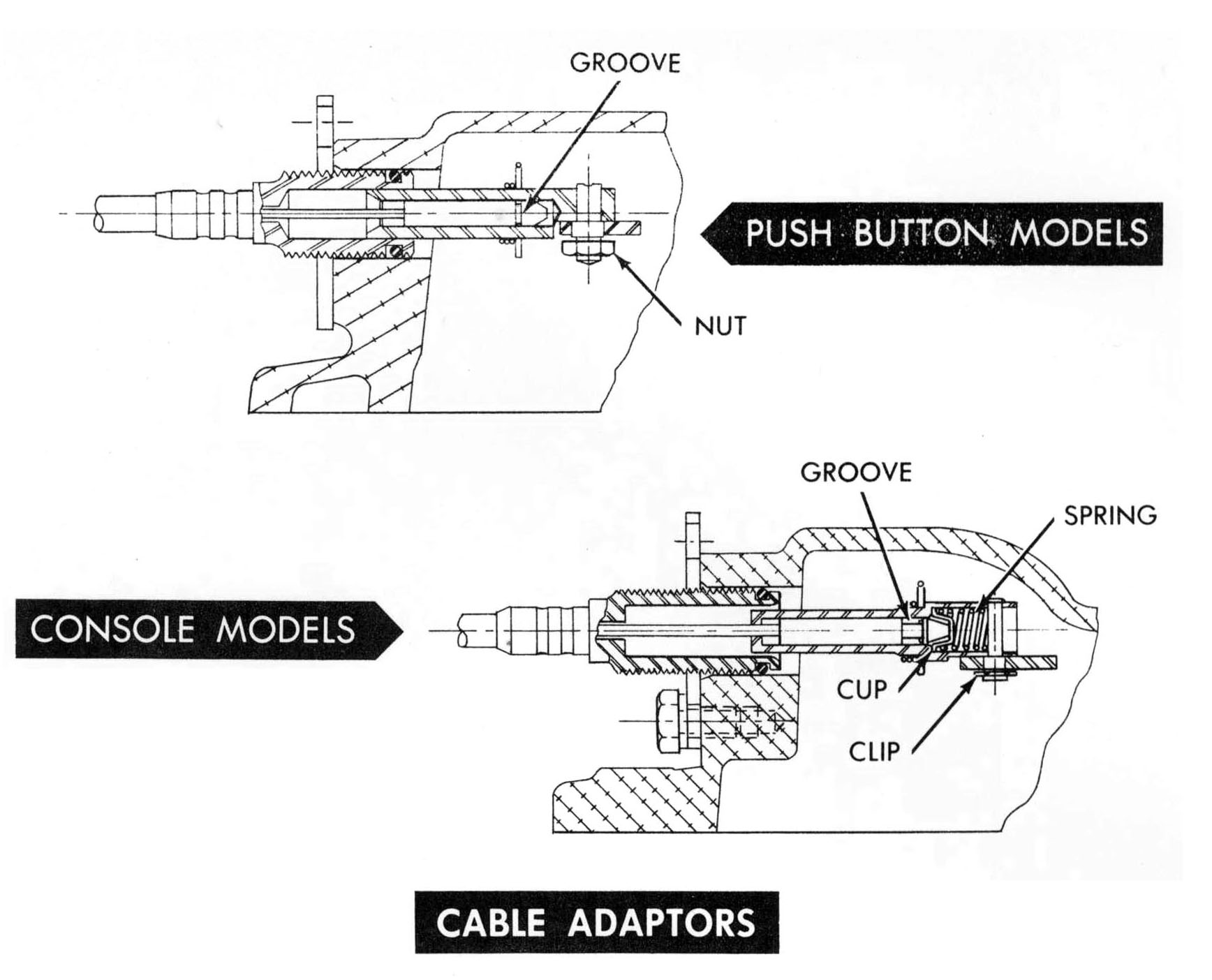
CABLE ADAPTERS Adapters and cables are not interchangeable between push button and console models. In console torqueflites, the cable adapter contains a small overtravel spring and cup. Also, the lock spring groove in the cable end is wider than on push button cables. The overtravel provision in console transmissions had to be made to accept the reverse�to-park travel of the cable after the manual valve is bottomed. The presence of the spring accounts for the change in shift cable adjustment at the transmission. |
|
|
Having trouble with printouts coming out way too small, or pieces of a document printing acro ss sev eral page s? Then go to our "How To Print Imperial Literature" page to learn how to print an item at the size you'd like. |
This page was last updated 13 January 2010. Send us your feedback, and come join the Imperial Mailing List - Online Car Club
