 |
|
Model 800: 1956 Imperials and earlier
Imperial Home Page -> Repair -> Accessories -> Gas Heater -> Page 4
 |
|
|
|
|
b.
Installation
Inspect relay assembly. Check fuse and replace with a 9-ampere fuse,
if necessary. The relay assembly is serviced only as a complete
assembly. Install relay and attach the ground wire to the front screw.
Connect the wires (Fig. 19).
Disconnect the two
wires from terminals at front end of heater assembly. Remove retaining1
screws, and raise the front end of case. Disconnect the two fuel
valve wires, and remove spark plus wire and grommet. Remove the case
upper half and the fuel line. Disconnect heater
blower hose with grommet and disengage exhaust pipe. Remove the rubber
adapter which connects heating housing (engine side) to heater.
Disconnect the two wires at the overheat coil and remove heater body. b. Installation
|
points. If the wire connections are
loose at the overheat switch, correct by soldering. If any of the other
conditions exist, replace the overheat switch as follows. Unsolder the
white wire at capacitor (condenser), and disengage both wires at cover
clip. Remove the two screws, and remove the overheat switch and wire
assembly. If the capacitor is to be replaced, unsolder the two wires at
the terminal block in cover and remove capacitor. Whenever the
overheat switch is replaced, replace the capacitor. Check rubber coupling
hose for visible damage or deterioration. Install heater body lower
half. Connect blower motor ground wire, with an external tooth
lockwasher between head of screw and wire terminal. Connect exhaust pipe
to heat exchanger tube. Insert heater burner blower hose on burner and
exchanger opening. Install spark plug cable on spark plug terminal,
positioning cable grommet in lower case. Install fuel line and position
grommet in lower case. Position heater case
upper half and connect overheat switch wires (black wire to coil cover
terminal and white wire to coil terminal, as shown in Figure 19).
Install heater case upper half, and place rubber adapter between blower
housing and heater case. Connect two heater wires at heater upper case. 33. SERVICING THE
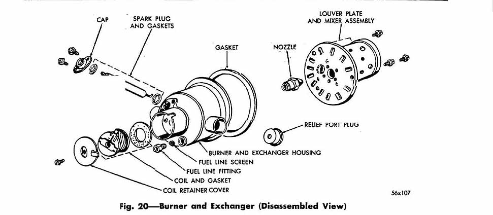
BURNER AND EXCHANGER a.a. Removal
|
This page last updated April 25, 2001. Send us your feedback, and come join the Imperial Mailing List - Online Car Club
