Imperial Homepage -> Repair -> Air Conditioning -> Dash Control Repair
This article provides tips on repairing the dash control panel for the Heat & Air Conditioning on a 1960 Imperial. While the directions and pictures shown here are specific to 1960, the controls used from 1957 through 1973 are very similar in function, and the information shown here could be applied to controls from any of those years.
The typical control panel consists of a series of pushbuttons (five in this example), a master switch that controls the vacuum and electrical connections for the system, a fan switch, and a metal bracket that attaches the controls to the dash.
| Click on any image to see a larger version! | |||
 |
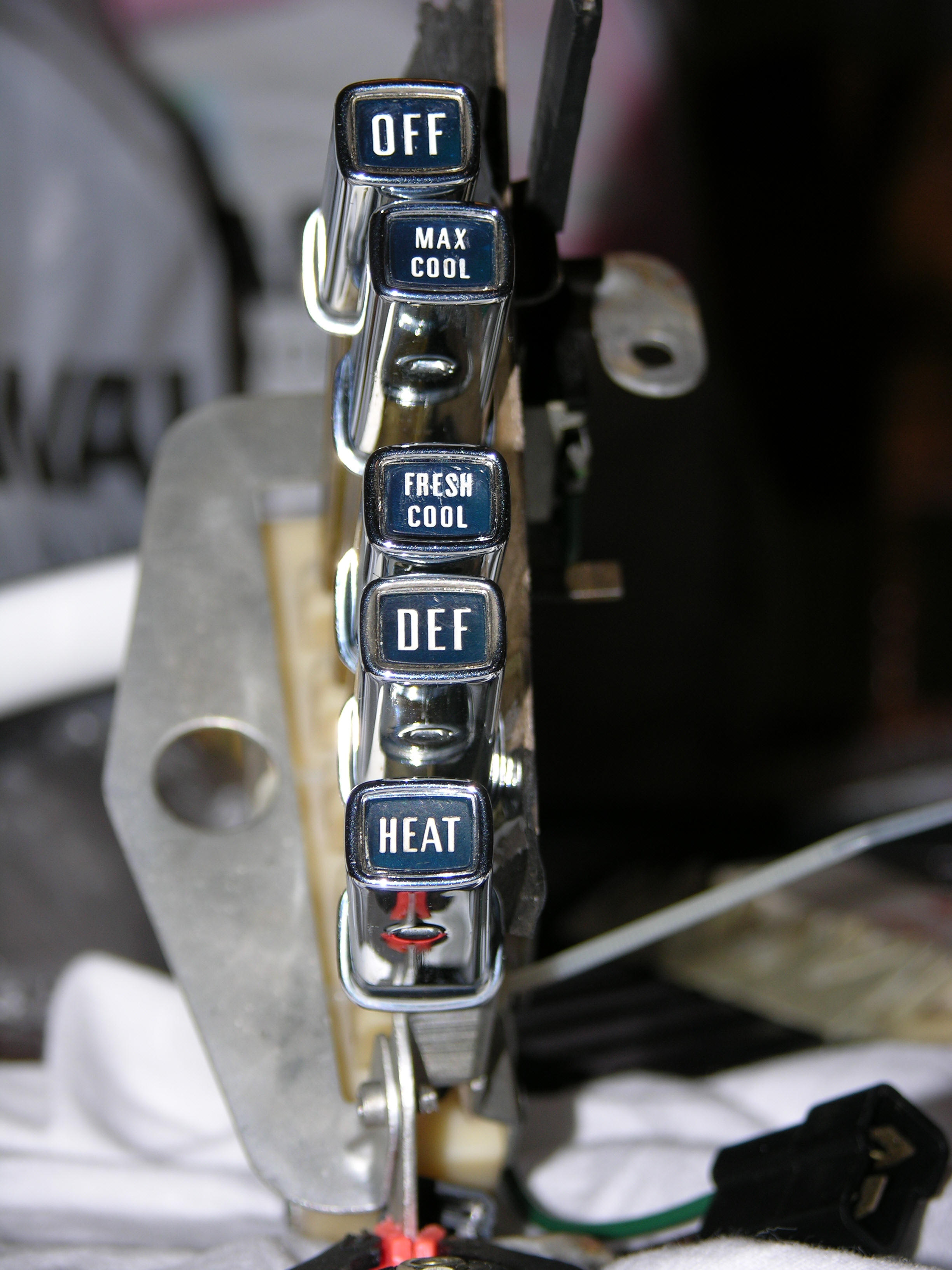
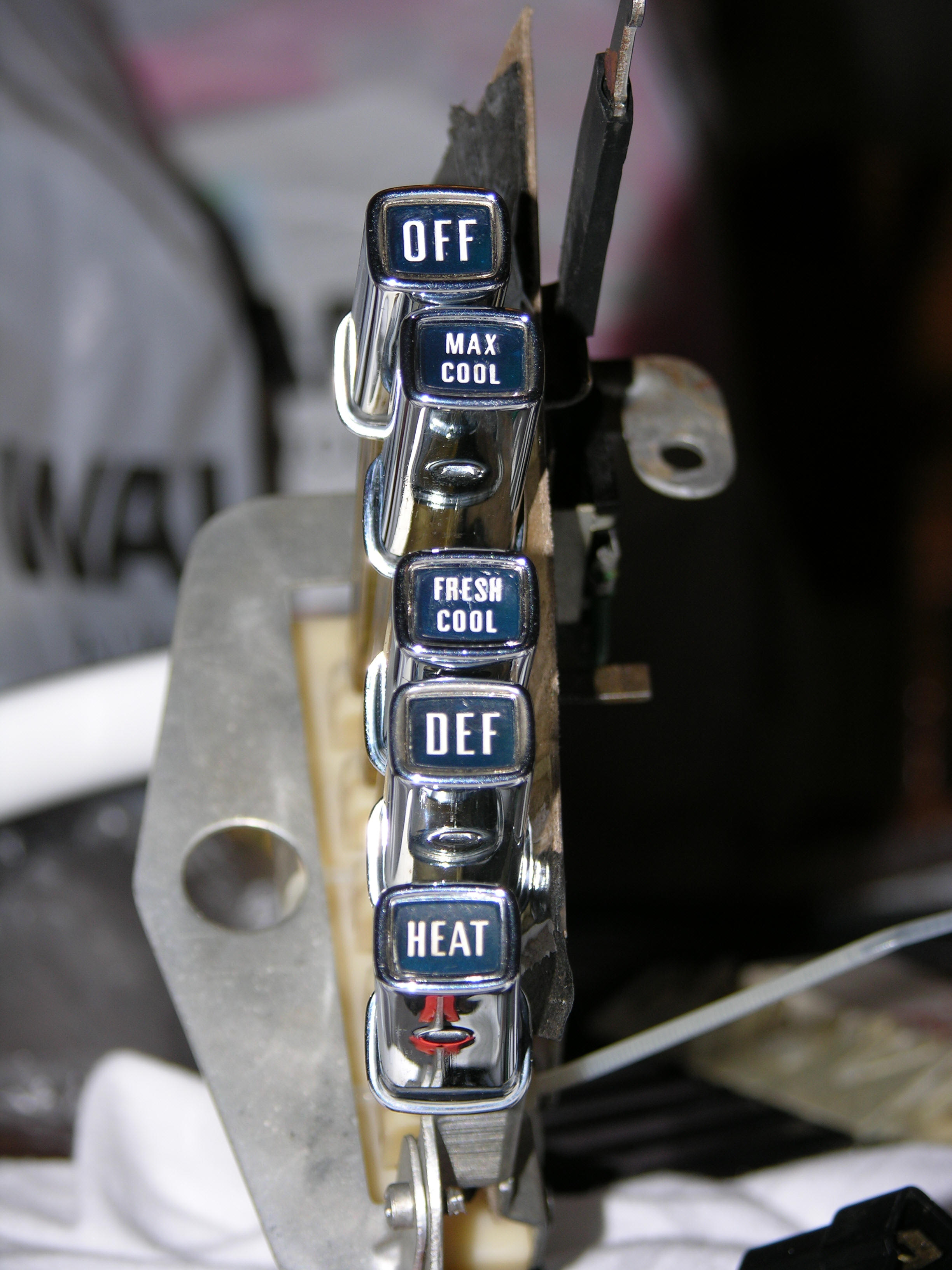
In this image, you can see the five buttons
to activate the system:
Obviously, if you remove any of the buttons during disassembly, you'll want to make notes of the order they go in. The buttons just snap into the connectors at the switch, so they can be easily pulled out and removed. Also note the circular hole in the bracket on the left side of the switch--this is where the light bulb attaches that illuminates the switches when the headlights are turned on. And take a close look at the lettering and chrome on the switches. By the time we're done, that will all look MUCH better as well. |
||
 |
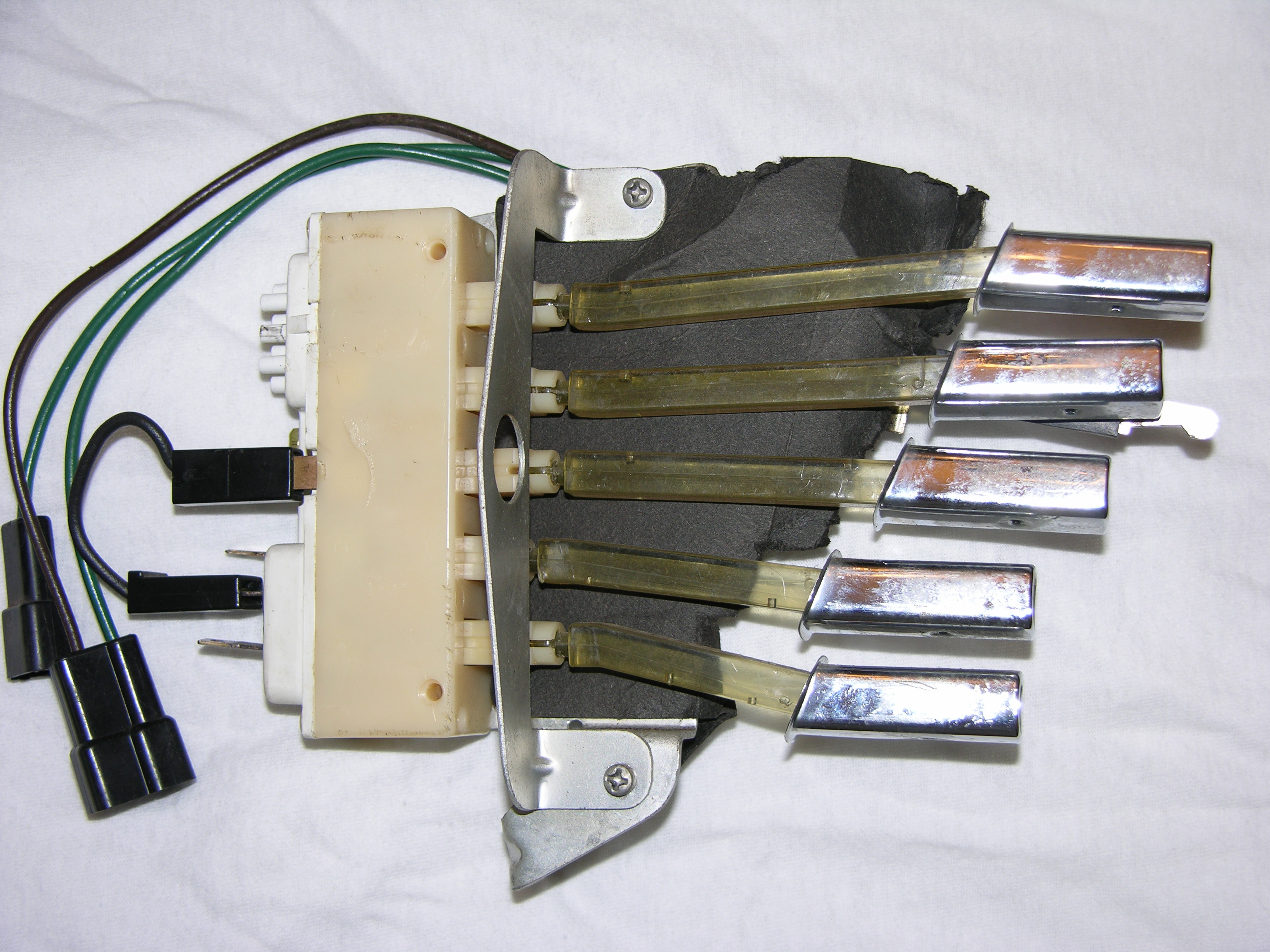
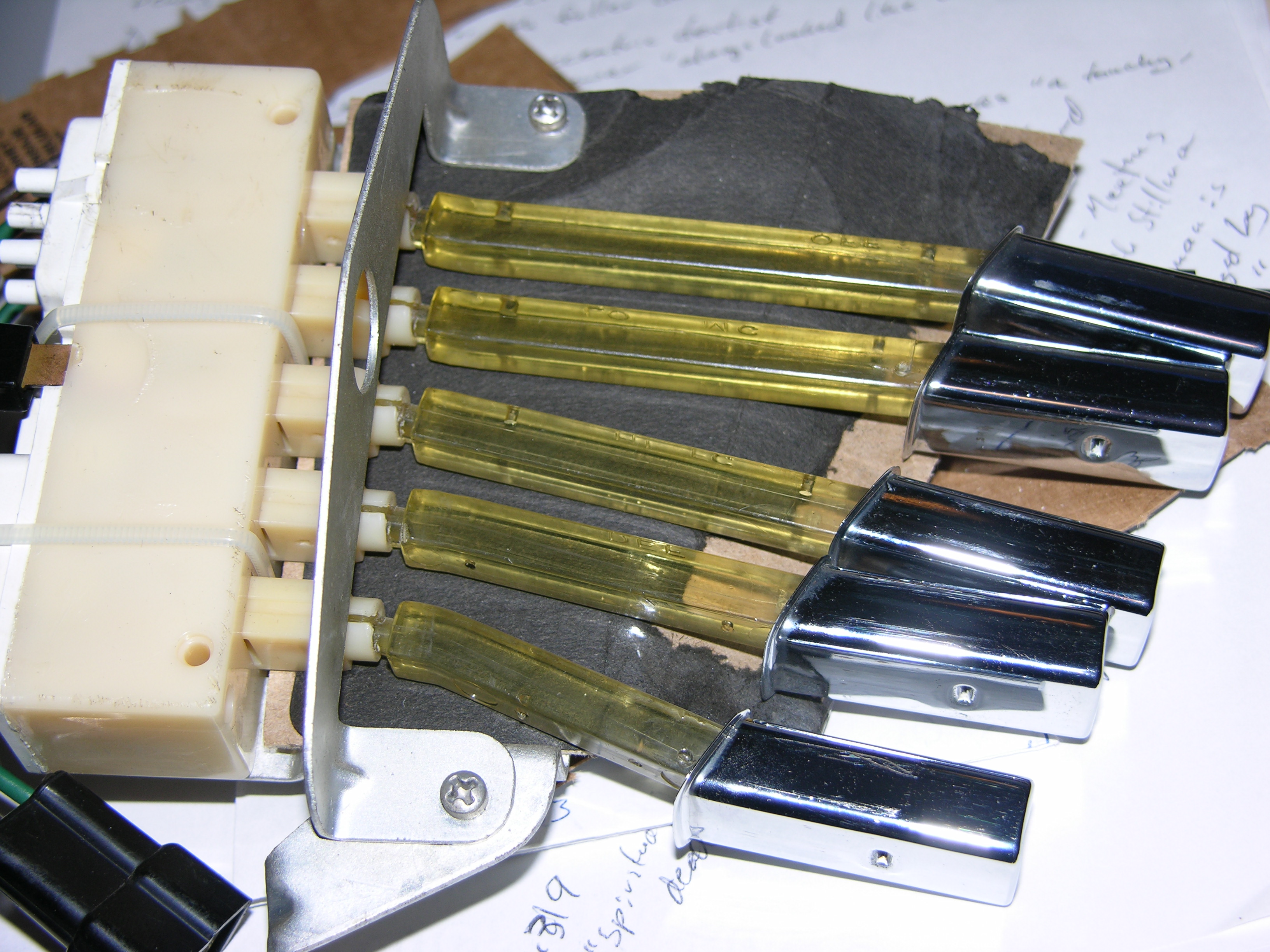
This photograph shows the switch viewed
from the side. At the upper left is the lever for the thermostat &
fan speed control. The on/off control for the fan is actually built
into the plastic switch body at the right. The fan is turned off
when the OFF switch is pushed, and is turned on when any other switch is
selected. When the thermostat lever is raised or lowered, it moves a
cable that is attached to the heater control valve (sometimes called a
water valve) to regulate the flow of hot water into the heater core.
The same lever is moved in or out to select Lo, Med, or Hi fan speeds. The plastic housing at the right of the assembly has seven vacuum connections at the top and three electrical connections at the bottom. The vacuum connections regulate the flow of air to either the dash vents, floor vents, or defrost vents, and also control the amount of fresh air and recirculated air. The electrical connections turn on the fan, as noted above, and also turn on the A/C compressor when MAX COOL, FRESH COOL, or DEF are selected. |
||
|
|
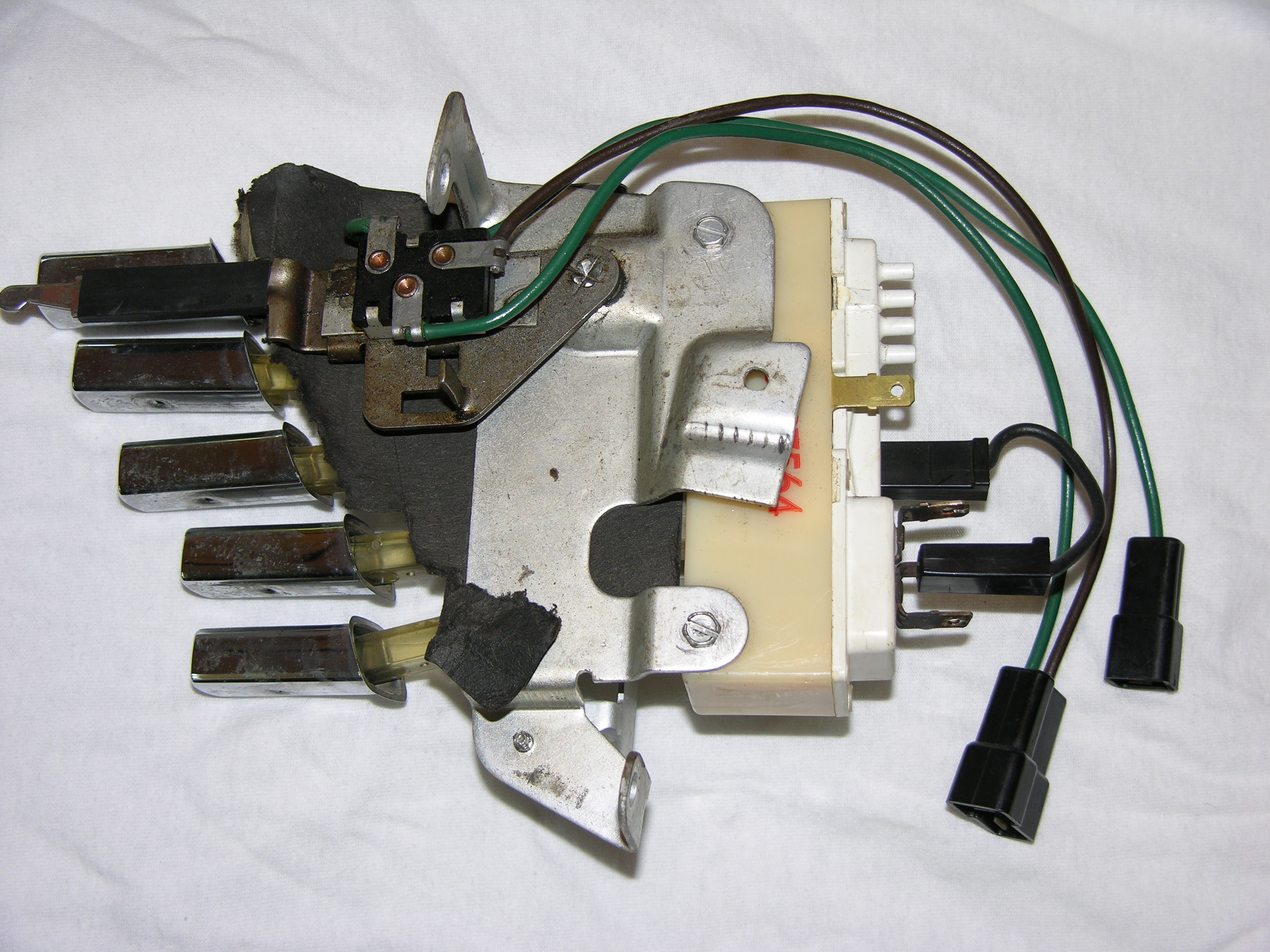
And here is the switch assembly shown from
the other side. The black cardboard is a shield to prevent the light
for the switches from "bleeding" into other parts of the dash when the
headlights are turned on. Most of the failures with these switches occur inside the plastic housing. The function of this switch assembly is similar for 1957 to 1973 cars, so the repairs shown here could apply to any of those years. If you believe there is a problem inside the plastic switch body, it is easy to open the housing by carefully trimming off the plastic tabs (but not the entire post!) that hold the white plastic panel (with the vacuum and electrical connections) to the tan plastic box. I used a hobby knife to trim back the plastic tabs. A good plastic glue, such as that used in building model cars, can be used to reattach the white plastic panel at reassembly time. |
||
|
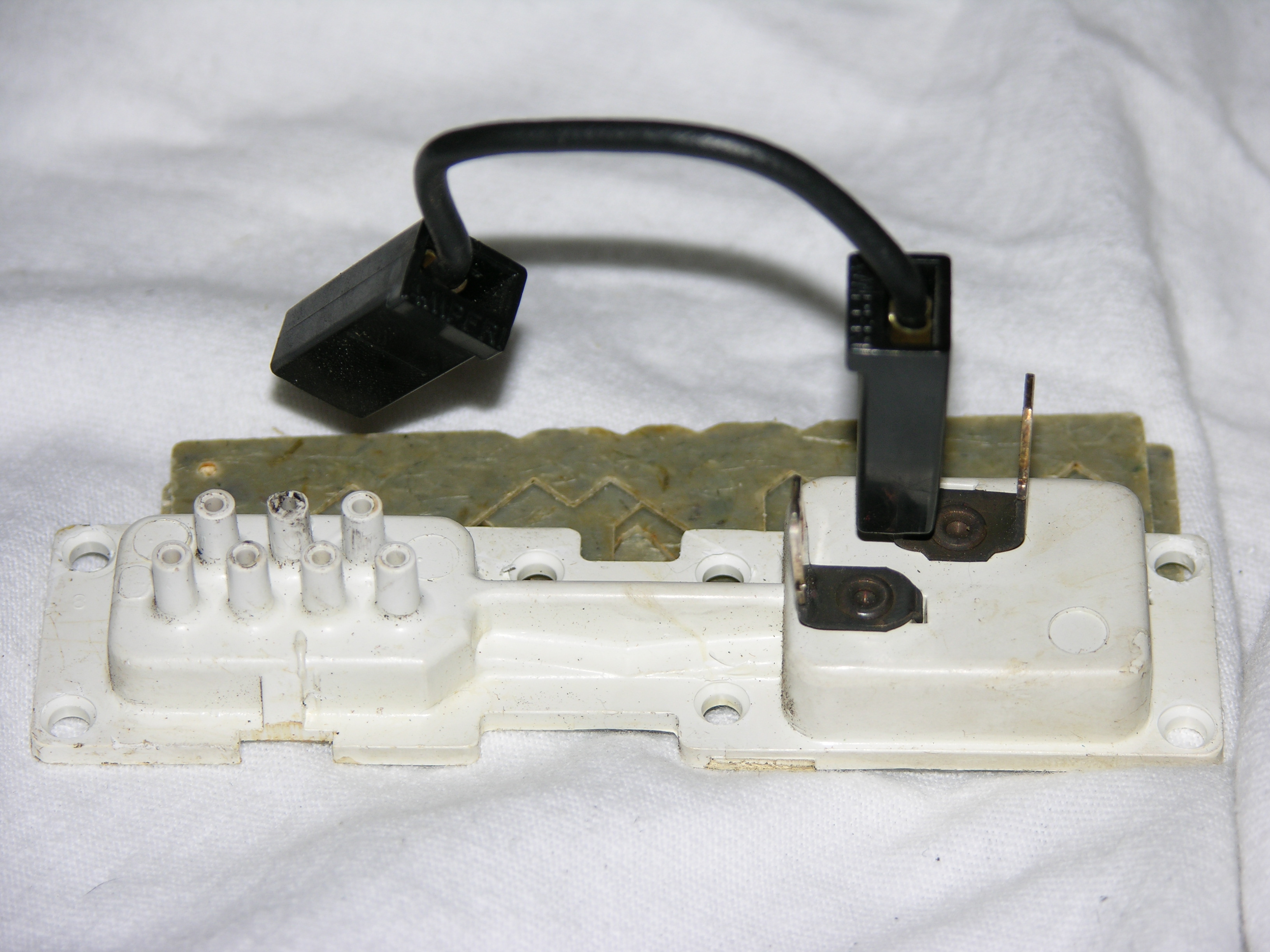
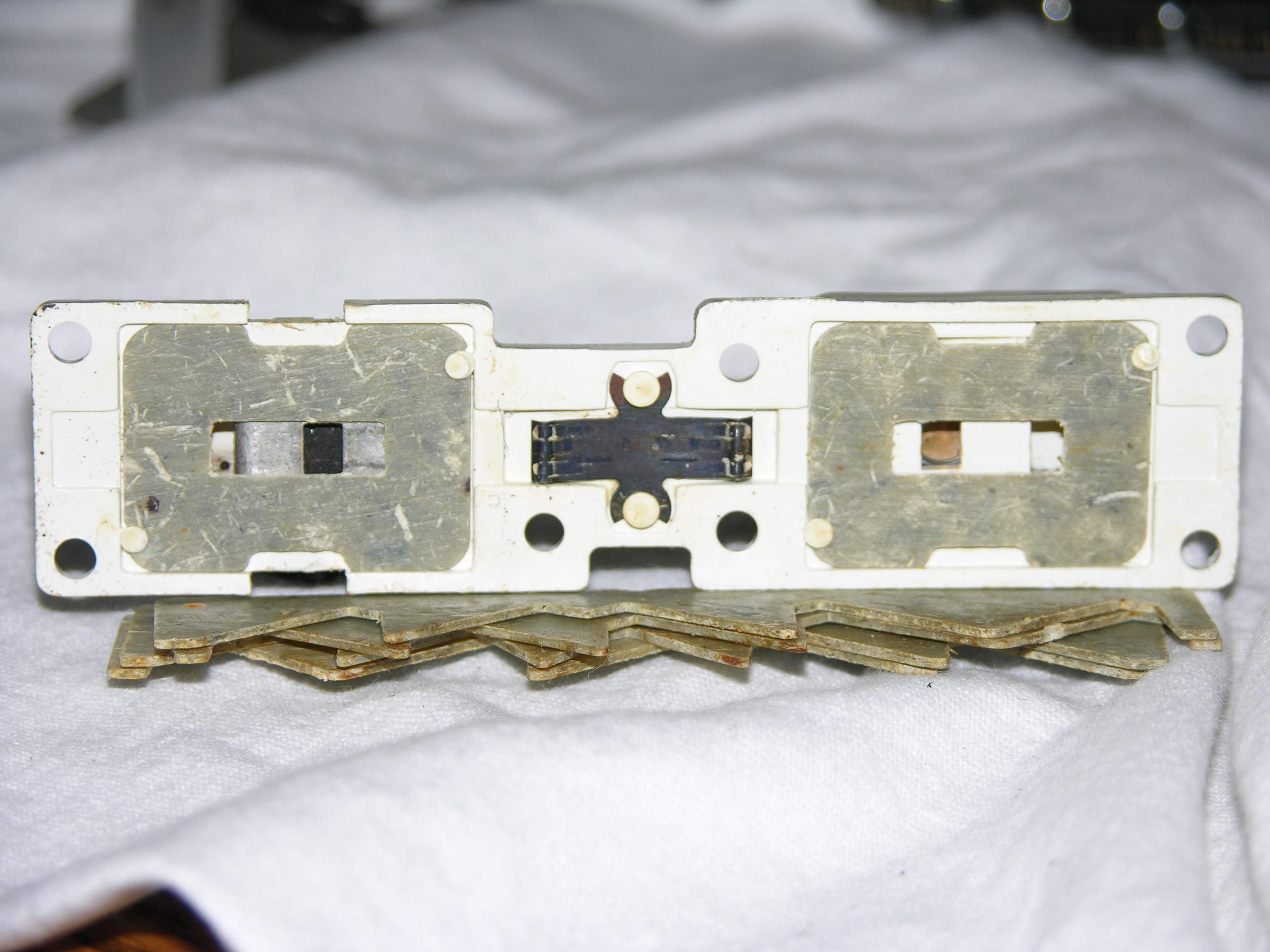
These two pictures show the white plastic
panel removed from the switch housing. When you open the control box, the top picture shows what you'll find! There are four sliders of different shapes (shown below in detail) with tabs that control the position of the vacuum connections and the electrical connections. On the left side of the panel shown here is the control for the vacuum connections, with the electrical connection control on the right. The spring in the center is a tensioner. The vacuum control at left and electrical control at right are both shielded by a grey plastic cover. This plastic is flexible enough to be carefully removed without breaking the white plastic posts that hold the covers in place. Chances are pretty good that you may need to open the one for the electrical connections, which will be shown below. |
||
|
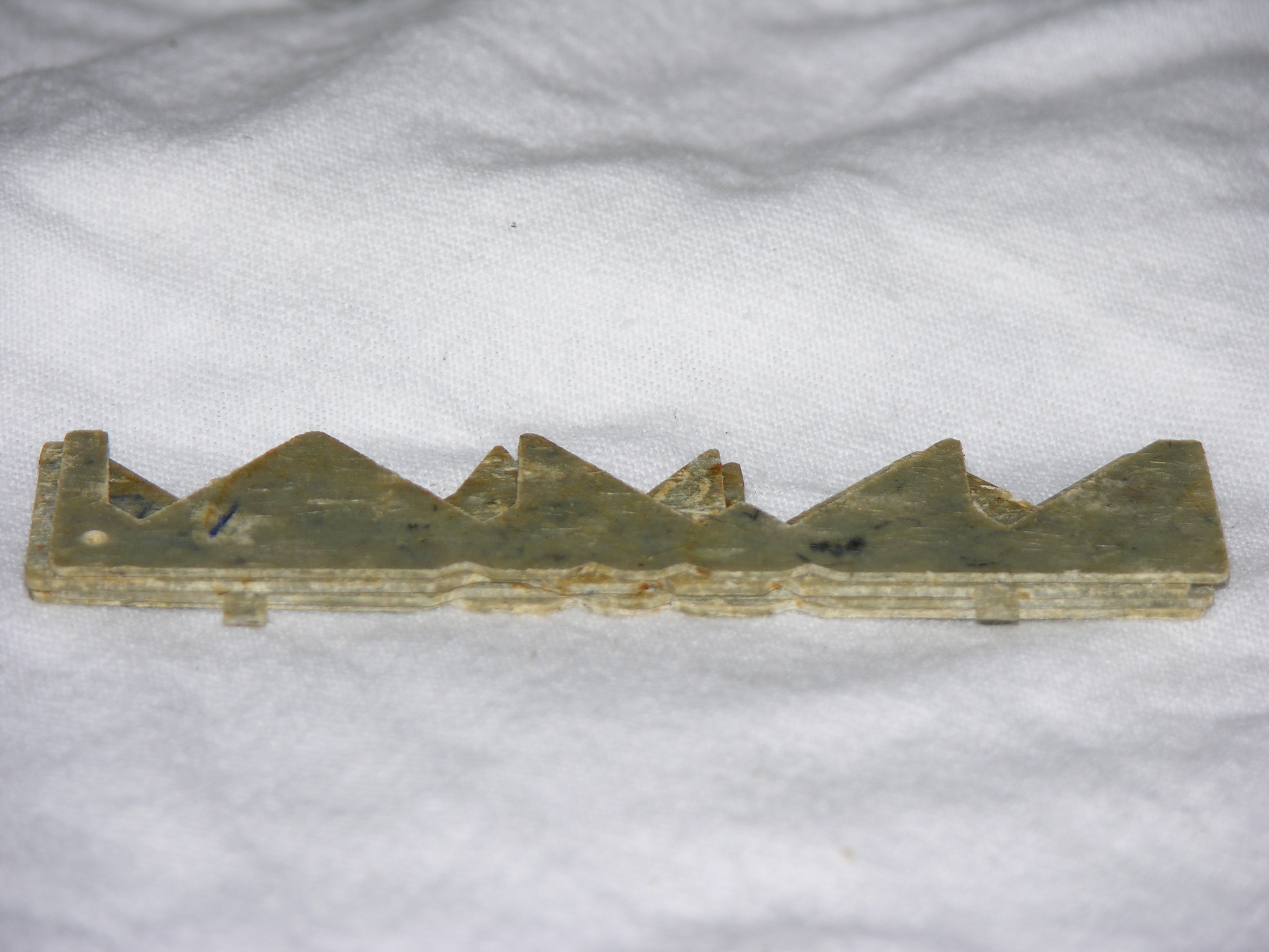
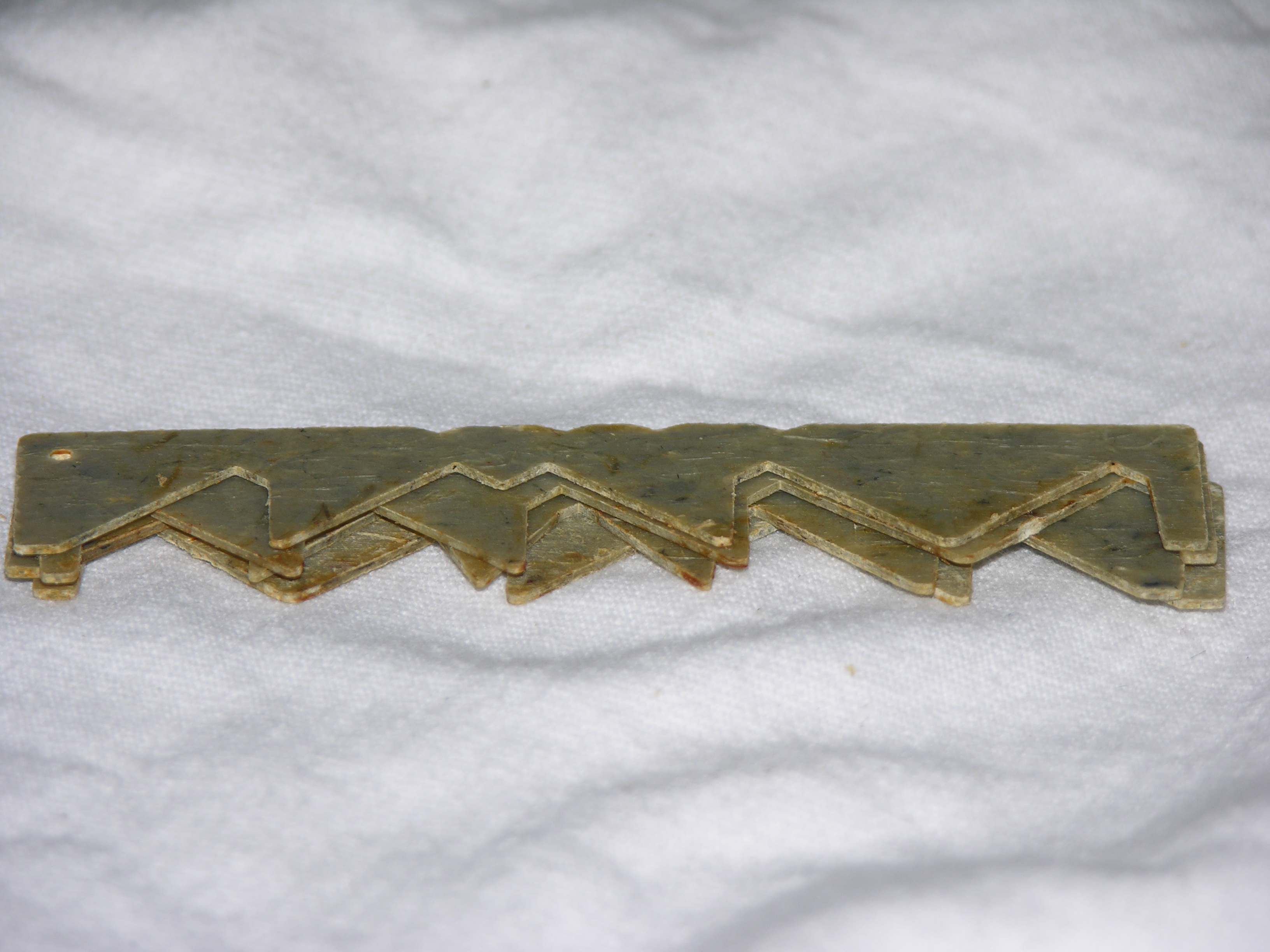
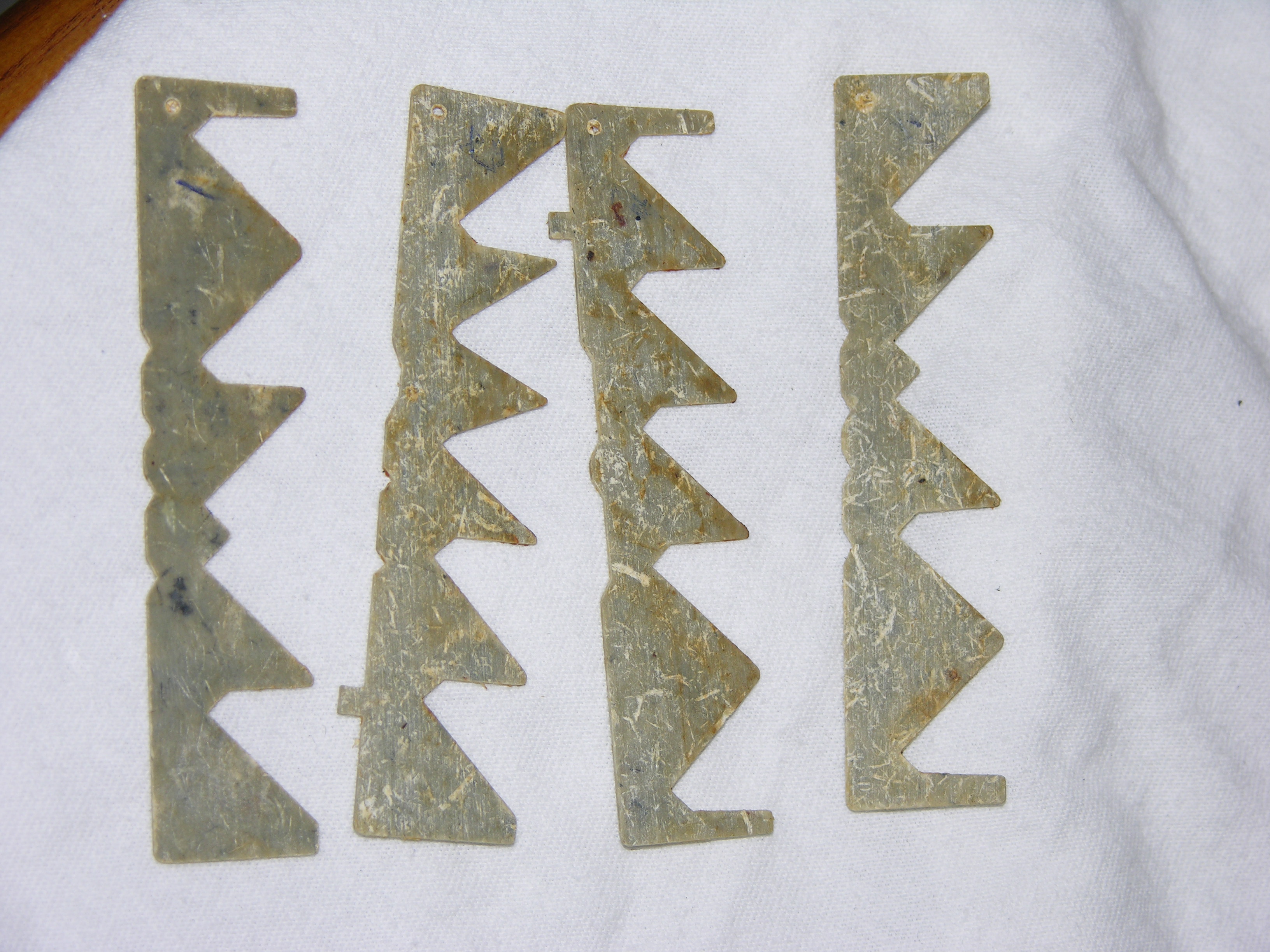
It's VERY important to keep the
sliders in the correct order and oriented in the same direction as when
they were removed. Use a marker or pen to number them, and make a
note to remind yourself of their orientation/position. If one of the sliders is damaged, find a suitable plastic (like a grocery discount card or old credit card) and use a hobby knife to cut out a replacement. |
 |
|
|
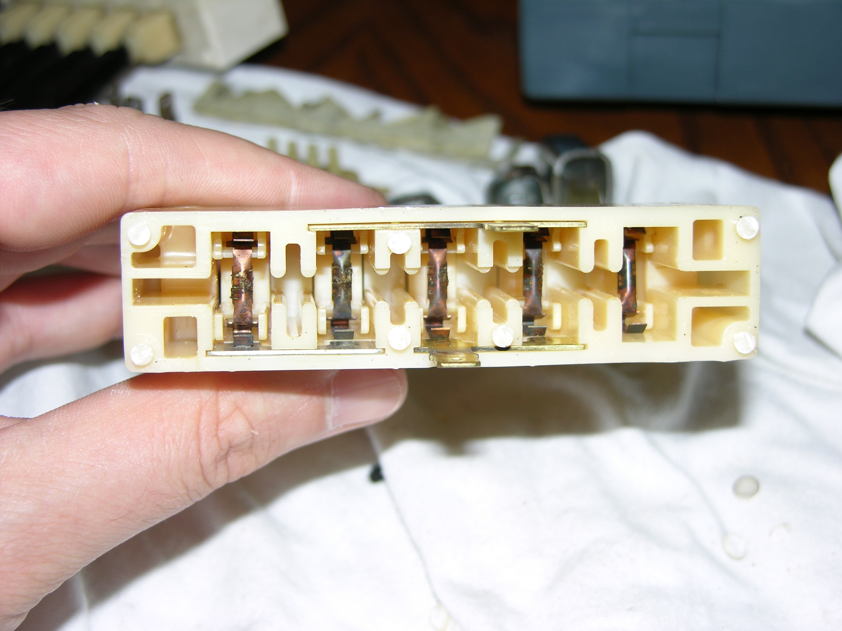
Inside the plastic box, you'll see the
other end of the pushbuttons. Each button is tipped with a metal
piece that acts as both a spring and as a snubber to push against the
sliders shown above. I would recommend placing a small amount of lithium grease on these snubbers before reassembly. Unless one of these pieces breaks, which is rare, there's not much to go wrong in this end of the switch. |
 |
|
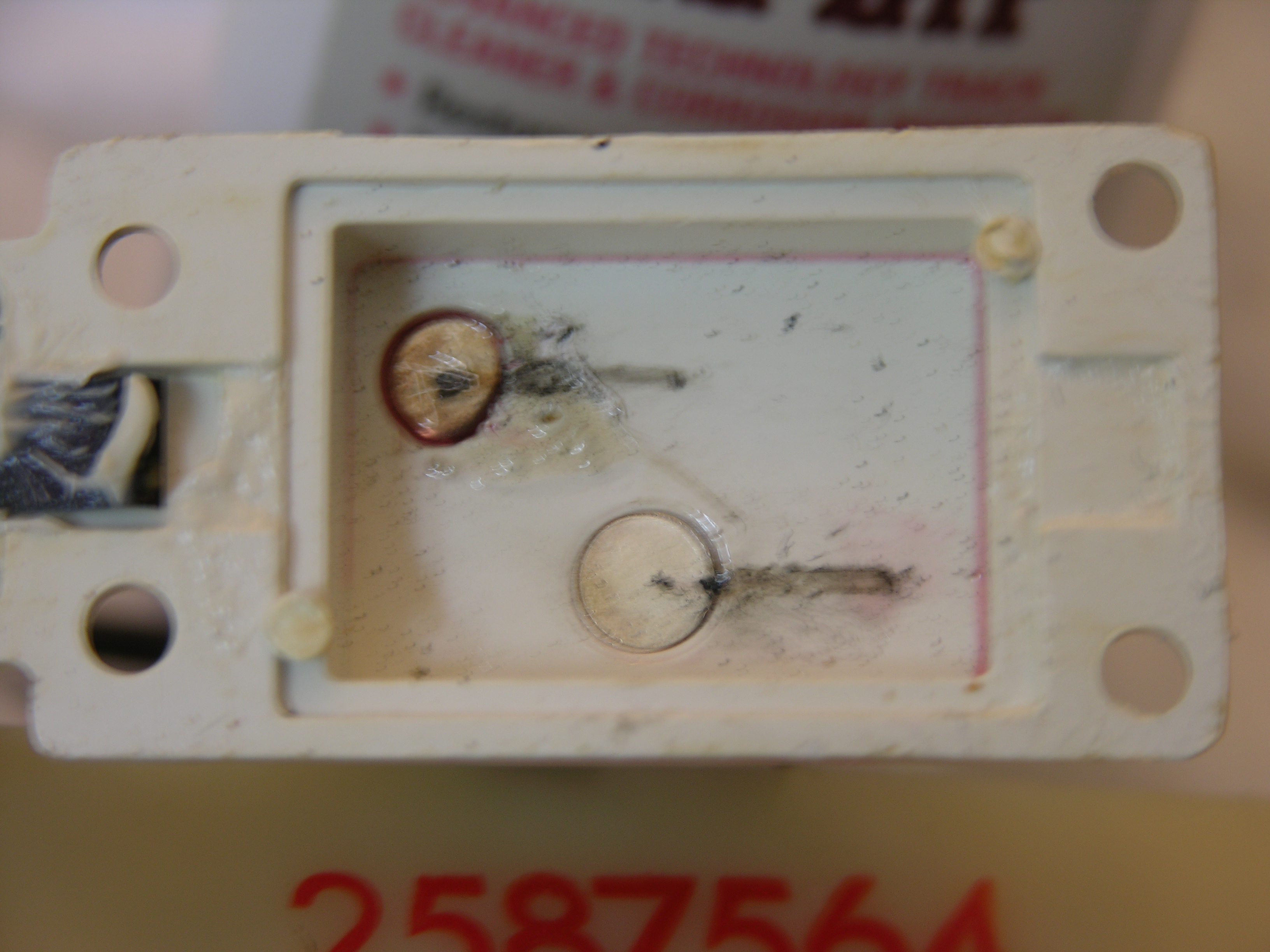 |
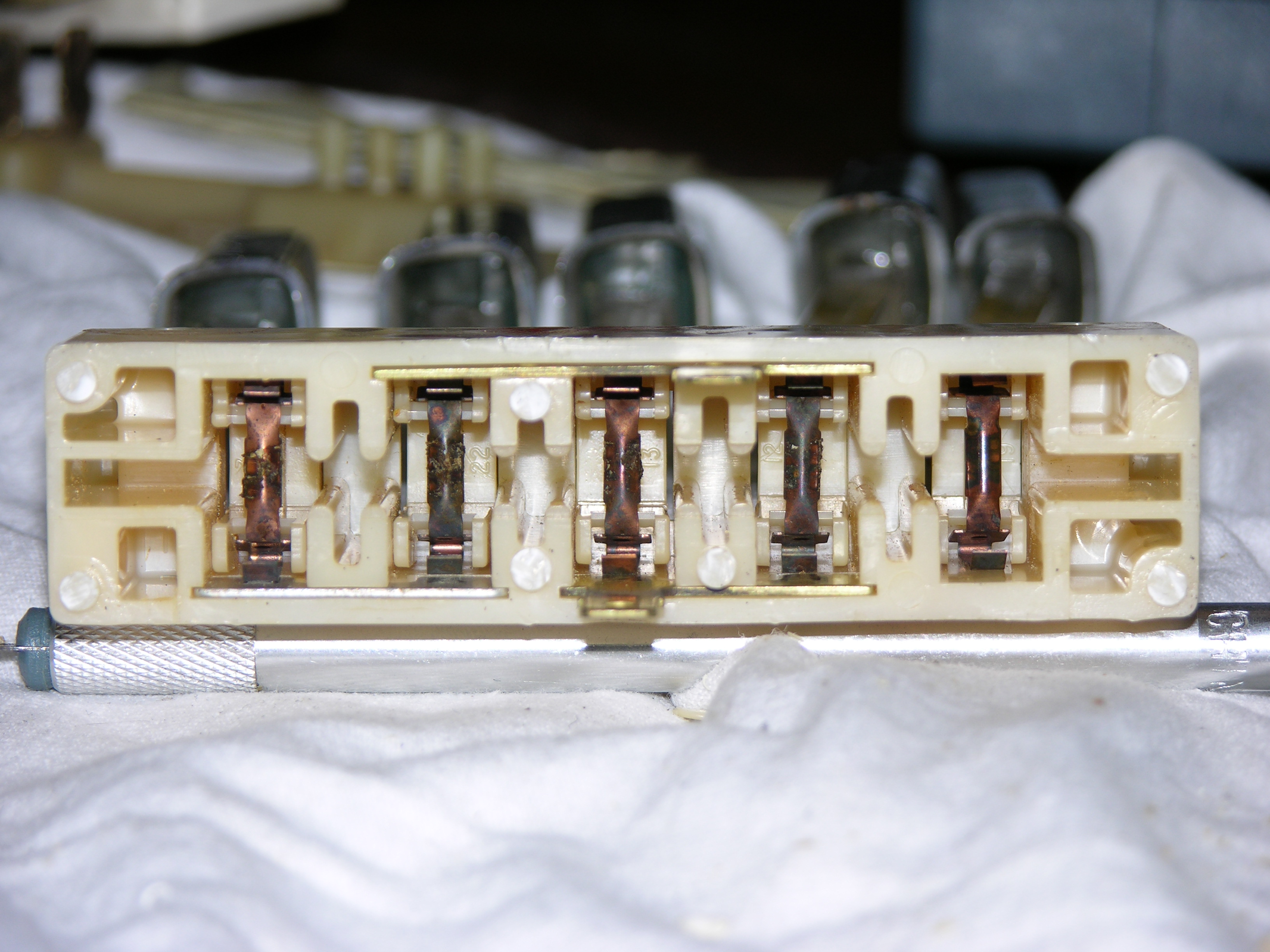
The problem with this switch was that the
OFF button would not go in. The cause was in the housing for the
electrical connectors. On the left are shown the two contacts for
the fan on/off switch. Notice that the contact at the top left has a
burned spot in the center, and the plastic to the right of it is bubbled
and scored. This contact had actually overheated at some point, and
as a result had sunk slightly into the plastic housing. The metal
slider that bridges these two contacts could not slide back out of the
resulting hole, so the OFF button would not push in. Cleaning the
contacts and filing the plastic smooth around the top contact solved this
problem. Electrical contact cleaner can be found at hobby shops. I'm a fan of Rail Zip, which is a product used to clean metal rails on model train sets. It works great in Imperial applications as well. |
||
 |
Remember how the buttons looked in the
first picture? Here are two shots of the buttons after cleaning and
touching up the paint. The metal cleaned up very well with a chrome
polish. The lettering on the buttons can be easily restored to a
like-new condition by using a paint stick. Paint sticks are
essentially felt-tipped markers that are filled with enamel paint, and can
be found at any hobby store. The paint readily goes into the grooves
for the letters. Once the paint dries, just use a cloth to rub off
any excess paint around the lettering (it actually rubs off quite easily
with just a dry cloth). Cleaning the chrome and restoring the lettering will really make an improvement in the appearance of the dash once the switch is reinstalled. This cosmetic part of the job could be done without even removing the switches from the dashboard. |
|
|
 |
At left is the switch reassembled.
Some thin cardboard was cut to shape to reinforce the broken, crumbled
cardboard shield. The white plastic panel was reattached to the switch box using model car glue. While the glue should prove more than sufficient to keep the switch assembly together, I threaded a couple of cable ties around the assembly just for added peace of mind. |
||
This page last updated July 7, 2006. Send us your feedback, and come join the Imperial Mailing List - Online Car Club