
Imperialists! I come to you this day (January 29, 2002, to be precise)
bearing tidings of great joy! The Budd Brake Supra Rotor Conversion was
successful! I will get on to The Solution below, but, as a refresher, you may
want to bone up on the background of this little project.
You see, I, like many of you reading this page, own an Imperial shod with the
now-infamous Budd Disk Brakes. These are 4 piston, fixed caliper brakes that
were somewhat revolutionary at the time, but as of late have become a Royal Pain
in the Ass to acquire parts for. The brakes were used on all Imperials made in
1967 and 1968, and most that were made in 1969, before the Chrysler Corporation
(hereby known as Ma Mopar) switched to the floating single caliper design for
the Fuselage Imps.
At any rate, one of the hardest parts to find is the brake rotors for these
setups. The rotors themselves are made out of unobtainium, a very rare and
highly precious material, which is generally sold by weight. As the rotors are
fairly heavy, this causes their price to be somewhere in the range of $300 to
$400 each.
In all seriousness, I believe that there may be an alternative to shucking out a
week's take home pay for a pair of lousy brake rotors. Going on some information
supplied to me by various members of the IML
(Imperial Mailing List), I decided to try using rotors from a Toyota Supra.
Specifically, I ordered a pair of rotors for a 1986-92 Toyota Supra. Now, of
course, you don't get something for nothing, so here's a breakdown of the
situation
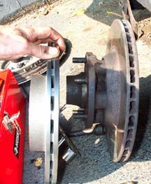
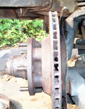
This picture and the one to the right show the two rotors side
by side. As you can tell, the outer diameter of the two rotors is identical, as
is the outer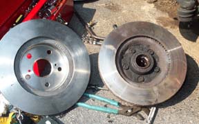 diameter. (11.8" and 7.3", respectively) Also, the bolt pattern is the
same (4.5"). The overall Supra disc thickness is about 0.005" less
than a new Budd rotor (based on my '67 FSM spec's), which is minimal and will
actually work out well as aftermarket pads are generally a little thicker than
those of the OEM variety. The venting is different, but if anything it appears
that the Supra rotor has a thicker disc surface. Of course, my Imp rotor has
been turned down so much its just about paper thin anyway. :(
diameter. (11.8" and 7.3", respectively) Also, the bolt pattern is the
same (4.5"). The overall Supra disc thickness is about 0.005" less
than a new Budd rotor (based on my '67 FSM spec's), which is minimal and will
actually work out well as aftermarket pads are generally a little thicker than
those of the OEM variety. The venting is different, but if anything it appears
that the Supra rotor has a thicker disc surface. Of course, my Imp rotor has
been turned down so much its just about paper thin anyway. :(
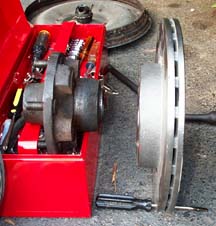
Remember what I said about not getting something for nothing?
Well, here's the kicker. The main 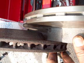 difference
between the Budd Rotor and the Supra Rotor is their tower height, or the
distance between the top of the disk surface and the top of the mounting flange.
You can see it in the picture to your left. The Supra Rotor (the shiny one) has
a tower that is 0.4" taller than the Budd Rotor.
difference
between the Budd Rotor and the Supra Rotor is their tower height, or the
distance between the top of the disk surface and the top of the mounting flange.
You can see it in the picture to your left. The Supra Rotor (the shiny one) has
a tower that is 0.4" taller than the Budd Rotor.
OK, so here's the situation: Somehow we need to delete the effects of this
additional 0.4" so that the entire assembly will line up correctly. There
are several ways in which we can accomplish this. We could remove
0.4" from the surface of the Supra disk tower. This would be the best thing
to do, as it would leave the Imp unmodified, but unfortunately the Supra rotor
is only 0.2" thick at the mouning surface at the top of the tower. So this
option is out completely.
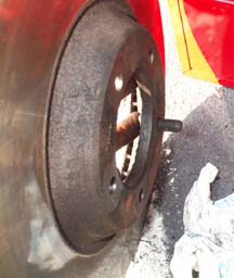
The second option would be to move the caliper assembly inboard (towards the center of the car). At first, I thought that this would be the way to go. Unfortunately, two things prevent this. First, the disc rotor would be 0.4" closer to the baffle, and would actually interfere with some protrusions on the baffle. (see picture below) However, the inner radius of the disk could be ground at a 45 degree angle to accomodate these protrusions, as they are all located near the inner radius of the disc
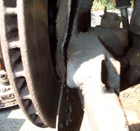
As you can see from the pictures, however, it is impossible to move the caliper inboard without grinding down either the caliper itself (entailing removing and machining the precious caliper- ick), or the caliper mounting surface on the car (entialing removing the entire mounting assembly from the car and machining it- double ick!)
The Solution!
OK, so we can't just machine down the Supra rotor tower 0.4", and we can't move the caliper inboard 0.4", so what's the solution? (sidebar: all engineering problems have solutions. Its just a matter of time and money. You may quote me on that.)
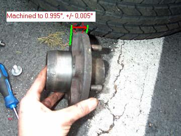
The solution is to machine down the face of the hub (which
bolts to the disc and thus locates the disc laterally with respect to the car)
0.4". As you can see from the above picture, we have the hub on the left.
The surface which mates to the disc must be taken down 0.4".
Before we do this, however, we must make sure that certain parameters will not
be adversely affected. First, lets look at the 5 bolts which hold the rotor to
the hub:
As you can see, the bolt protrudes through the current rotor 0.7". thus, we
need to make sure that the tapped depth in the hub is at least 0.7" plus
0.4" or 1.1". It is in fact 1.2", so we are safe here. When we
machine 0.4" off the hub, it will be 1.1" minus 0.4" or 0.8"
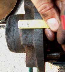
deep. You can see by the picture on the right my attempt to show a measurement
of the hub width. *sheepish grin* The flash overpowered the numbers on the rule,
but you can take my word for it that the hub is 1.4 inches wide, thus the tap
must be going all but 0.2" into it.
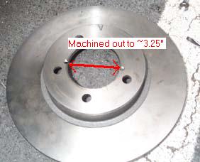
There are a few other parameters which must be taken into
account as well. As you eagle-eyed viewers may have noticed, the hole in the
center of the Budd rotor is larger than the hole in the center of the Supra
rotor. Specifically, the Budd rotor hole is 3.25" and the Supra's is
2.3". So this hole must be machined larger.
The extremely eagle-eyed viewers among you may have also noticed that the
Budd rotor has smalle holes for the mounting bolts to pass through. To be
precise, the 5 mounting bolt holes in the Budd rotor are 0.5" in diameter,
while the Supra rotor holes are 0.6" in diameter. In order to use the same
diameter bolts (and avoid drilling out and re-tapping the hub, and using
oversize bolts) I will likely put some sort of a collar around the bolt to keep
it centered.
Since the bolt itself is smaller in diameter than the one purportedly used by
Toyota in the Supra application, the head is also smaller and while it will not
pass through this 0.6" hole, it would be wise to use a washer to provide
some extra surface area for the bolt to hold the rotor. This has the added bonus
of making the bolt a little shorter as it protrudes through the rotor; indeed,
we would need to do this as the tower top of the Supra rotor is 0.2" thick,
and the Budd rotor tower top is 0.4" thick.
1/29/2002: Well, its been a tad longer than the few weeks I
promised a few months ago, but I got bogged down with other projects on Silver,
and then the weather began to turn wintry...as it will sometimes do here in the
not-too-balmy Middle Atlantic. Still, these last few days have been uncharacteristically
balmy (In the 70'S!!!) so I managed to bang out the remainder of the project.
As much fun as I had doing all the measurements and calculations above, in the
end I just ended up taking the old Budd rotor/hub setup to Grizzly Machine Shop
(near Elkridge, Maryland) along with a spare hub and the Supra rotor, and told
them, pointing first to the Supra rotor and hub, and then to the Budd rotor and
hub, "Make this look like this." I can be so eloquent at times.
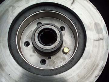
Fortunately, it worked! They machined the hub face down as I described below, so
it now looks like this:
The arrows indicate what was left after the machining operation; this is what I refer to as the hub thickness. I also had them enlarge the center hole of the Supra rotor, as seen in this picture:
Now the Supra rotor will fit over the Budd hub, and the bolt holes line up as
you can see by this picture:
mentioned above the need to use a collar around the bolts, but
this does not appear to be necessary. The bolts with the lockwasher holds the
rotor well. Also, a little tip: When tightening or loosening the bolts which
secure the rotor to the hub, place the hub into the wheel and tire, thus the
wheel and tire provide you with excellent leverage to remove or snug the bolts!
Now, at this point several things happened. First, I discovered that, contrary
to my initial prediction, the original bolts were too long, and bottomed out. So
I had to go to Home Depot to scrounge some 1" long 7/16" diameter fine
thread bolts. Well, amazingly the Depot had them, but only as Grade 5 bolts.
Desperate, I bought them, thinking the Grade 5 would be sufficient to test the
setup out until I could procure some Grade 8 bolts. I also bought some
lockwashers on the off-chance that the 1" hardware was still too long.
Which it ended up being. Huzzah for forethought. Anyway, I got the whole bloody
mess together and installed it on the car.
 So
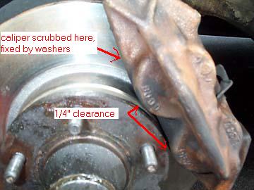
far, so good. However, here I ran into another "issue". It seems that
they had machined a tad too much off the hub face, and the outboard face of the
rotor was now barely scrubbing the caliper body. So, I had to move the caliper
outboard slightly to compensate. Thankfully, this was easily accomplished by
inserting a washer apiece between each of the caliper's mounting bolt holes and
the mounting bracket on the suspension arm.
So
far, so good. However, here I ran into another "issue". It seems that
they had machined a tad too much off the hub face, and the outboard face of the
rotor was now barely scrubbing the caliper body. So, I had to move the caliper
outboard slightly to compensate. Thankfully, this was easily accomplished by
inserting a washer apiece between each of the caliper's mounting bolt holes and
the mounting bracket on the suspension arm.