Imperial Home Page -> Repair -> Electrical System -> Switches -> 1956 Window Switch Repair
(Click on any small image to see a larger view.)
Thanks to Elijah Scott and Dick Benjamin for sharing their switch repair tips with me!
If you have a window switch like mine, where the chrome still looks fine, but the switch doesn't operate, is tricky to get to work, or is lazy to return to neutral, you can bring it back to "like new" operation. I'll be demonstrating how to rebuild the 1956 driver's master switch, but you can apply the same ideas to the simpler single switches, and other years such as 1951-1959, as well.
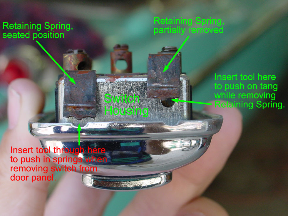
Step 1: Remove switch from door panel. Very easy to remove, without having to remove the door panel. There are (4) spring clips that hold the switch assembly in place, so just gently pry it out by accessing the slots in the side of the switch. I used a small Allen wrench, but you could use anything that fits. It shouldn't take a lot of force to remove, and if it seems like it's stuck, try pushing in on the spring clips as you gently pry the switch out.
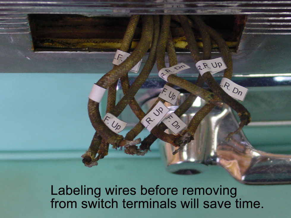
Step 2: Label the wires. Just makes it simpler later on. You could color code with paint to match the factory wiring diagram (I sure couldn't see any traces of color on my wires!), or just print out some labels like I did.
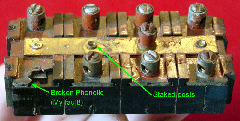
Step 3: Remove the wires from the terminals. Don't make the mistake I did with one screw terminal. The set screw was tight in the "right rear down" terminal, and I applied too much force trying to break it loose, causing the phenolic (plastic) piece that retains it to break instead. More on that repair later.
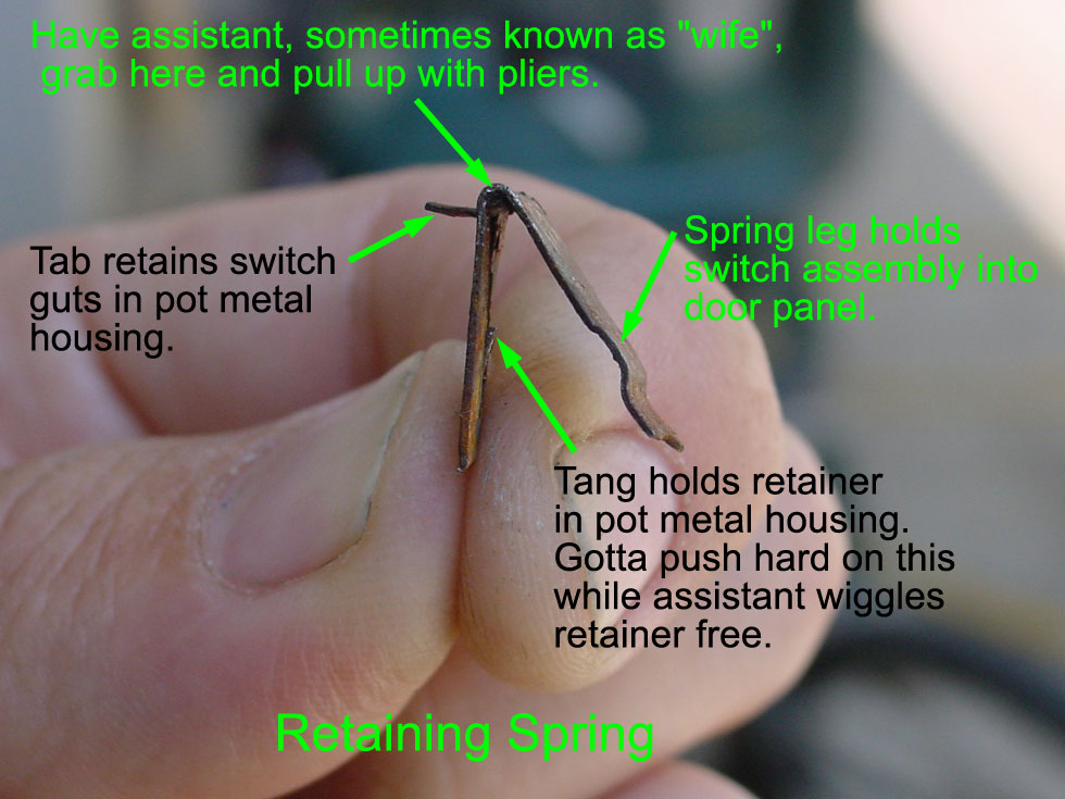
Step 4: Remove the (4) retaining springs. This might be the trickiest part of the whole job, but it's not bad if you have someone help you. You have to insert a tool, like a small Philips screwdriver or a pin punch, through the hole in the side of the pot metal switch housing, by first prying "up" a little on the spring leg to gain access, and then push hard on the retaining tang to allow it to slip past the hole while your assistant pulls and wiggles the retainer out with a pair of pliers. I was able to get a couple of them out myself by just pushing and prying up simultaneously with the pin punch, but the other two were easier with some help.
Step 5: Remove the (4) switches from the pot metal housing. Piece of cake now that you've got those retaining springs removed.
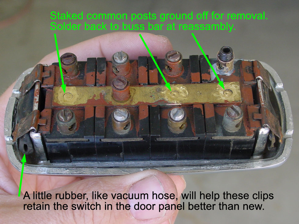
Step 6: Remove the brass buss bar. To do this, you'll need to grind away the swaged heads of the (3) commons as shown, until you can pop the brass bar free.
Step 7: Separate the individual switches. The only thing holding them together at this point are some Lego-like interlocks on the sides, and possibly the brass buss bar. Gently lift up on the bar to free, if necessary, and pull apart.
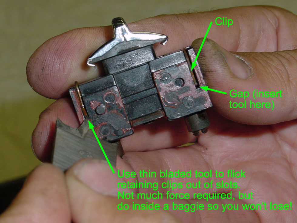
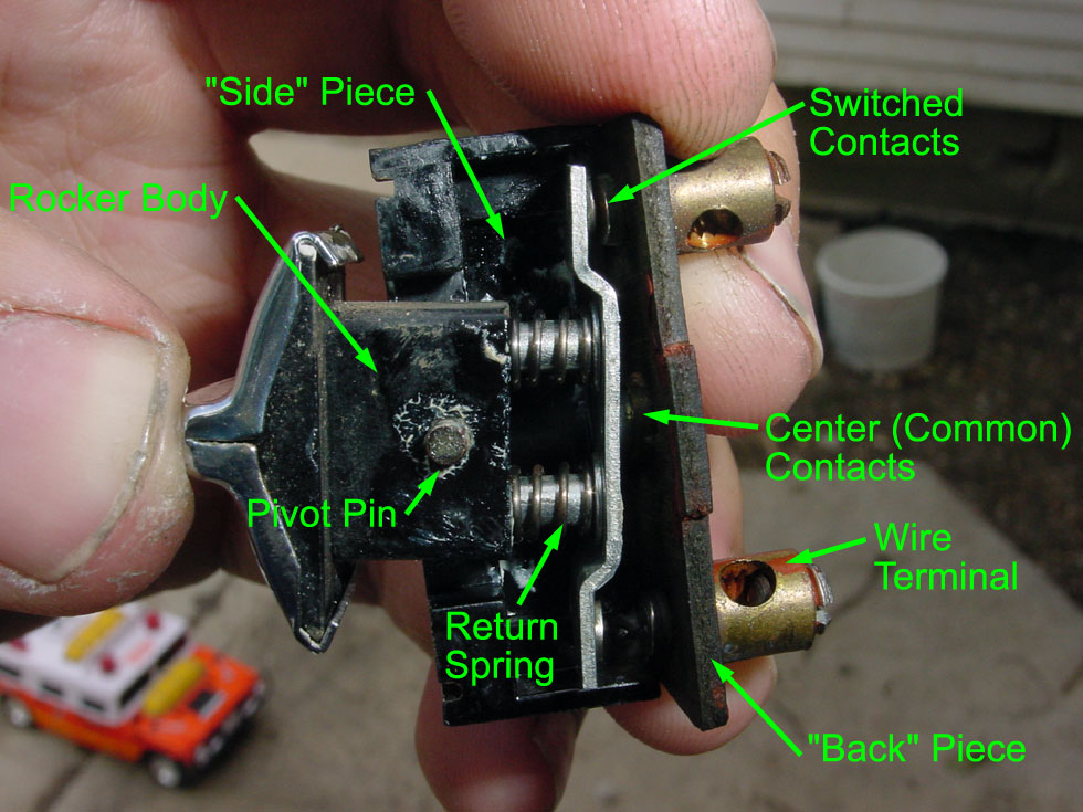
Step 8: Disassemble each switch. Take a small, thin, pointed tool and insert it under each retaining clip and pop off. I did this inside the plastic baggie I was using to store the small parts so I wouldn't lose it when it went flying. Once the clips are off, the "sides" separate easily from the "back", which is the piece with the stationary contacts. Be careful not to lose any of the small parts, such as the return springs, or the pivot pin, which can easily fall out of the switch rocker body.
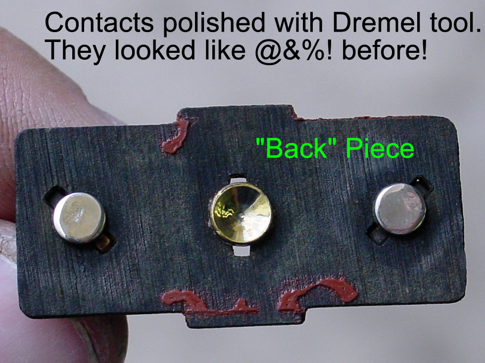
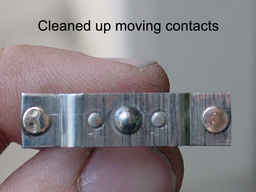
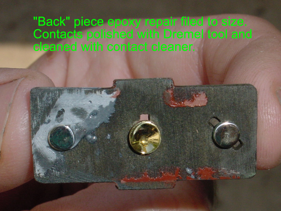
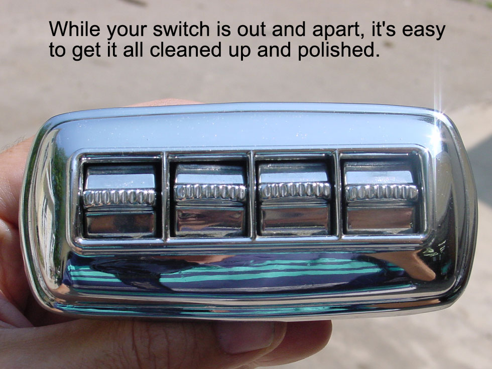
Step 9: Clean the contacts. I used a Dremel tool with a small polishing wheel and some compound to buff all the contacts to a shine, then cleaned with electrical contact cleaner.
Step 10: Make additional repairs as necessary. Here were mine:
Repair A: One of my switches in particular felt "lazy" in returning back to center, so I carefully stretched all the return springs a little.
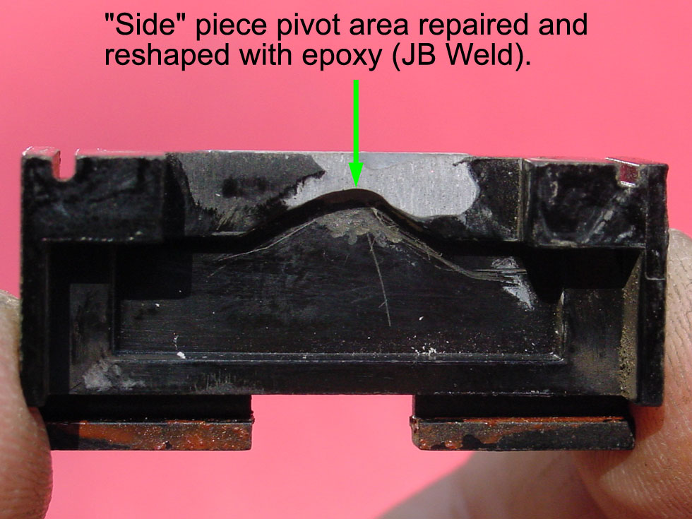
Repair B: My driver's switch had gotten to the point where no matter how you wiggled and pushed on it, it wouldn't make contact. The cause was a completely worn out/broken pivot point in one of the "side pieces", which I repaired with JB Weld (metal filled epoxy). After curing, I filed the edges back square, and used the Dremel tool with a small stone to cut the pivot shape back in. As you can see, it wasn't a perfect looking job, but it works great. (The whole area was completely "gone" before the repair.
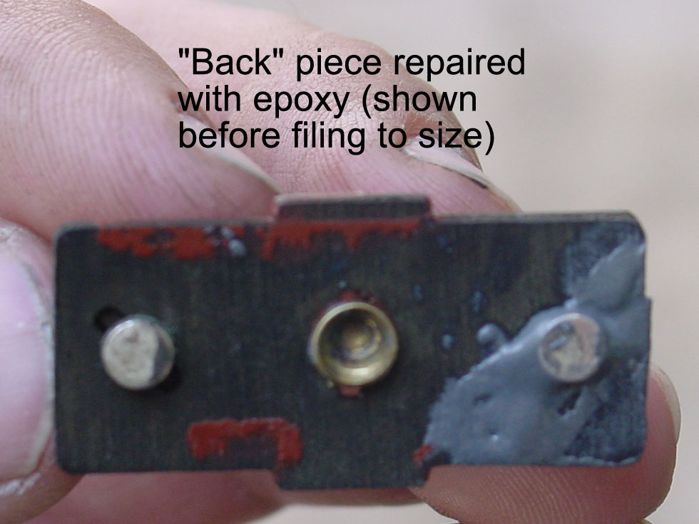
Repair C: The phenolic "back piece" I had broken earlier by stupidly applying too much torque trying to loosen a set screw holding in one of the wires. The JB Weld worked well here, too. Just clean everything well with contact cleaner before applying the epoxy. (Note: Dick Benjamin points out that JB Weld is slightly conductive, so unfilled epoxy would be a better choice if there's a chance of your repair bridging between the common and a switched contact.
Step 11: Clean everything else. What the heck, spray all the old dust and grease away with some contact cleaner for good measure. (Remove the pivot pin from the rocker body, or it will come out when you spray it!)
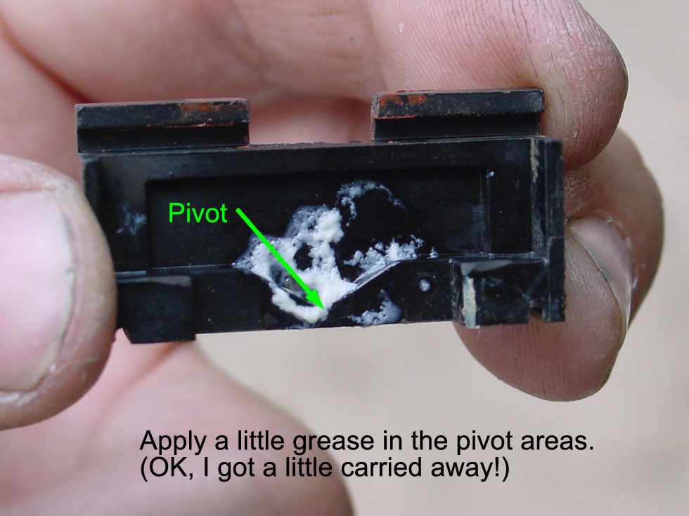
Step 12: Lightly grease the "side piece" pivot areas and pivot pins. I used a quick shot of Lithium grease.
Step 13: Assemble each of the (4) switches. The picture below shows how the "guts" go back together. Then slip the other "side piece" in place, and hold together while you grab the retaining clips.
Step 14: Install the switch retaining clips. By these I mean the light ones that hold each switch half together; they pop on easily without the need for a tool.
Step 15: Test each switch with a meter. Better to find out now that something is wrong, rather than after you have everything back together. Mine all tested great, with most registering less than 0.5 Ohm, and the worst reading 1.8 Ohm. Yahoo!
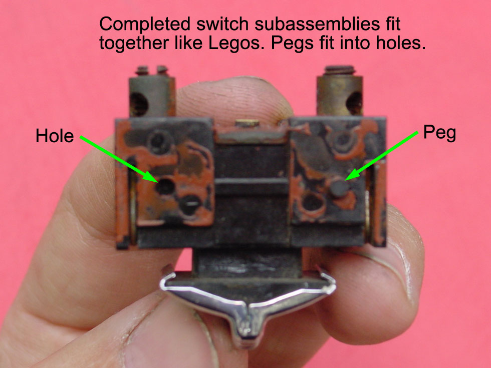
Step 16: Assemble the (4) switches together. They just interlock with alternating pegs and holes sort of like Legos. Fit the buss bar back over the posts at the same time.
Step 16: Solder the buss bar to the (3) remaining posts. Or solder it after you've got it back in the housing--your choice.
Step 17: Insert the (4) switch sub-assembly into the pot metal housing. Just slide into place.
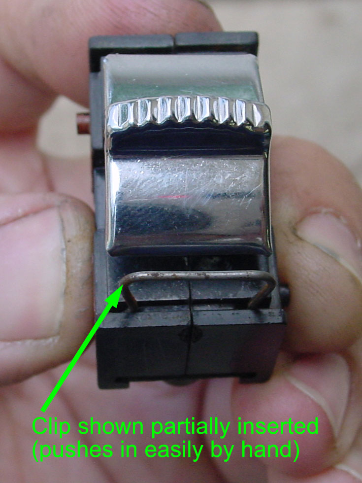
Step 18: Install the retaining springs. These push between the (4) switch sub-assembly and the pot metal housing. Much easier than they come out, just push in by hand until you hear a "click". Optional: insert some short pieces of rubber behind the main spring legs to help them retain better in your door panel.
Step 19: Re-test each switch. This time you'll also be verifying that you've got good soldered joints between the common posts and the brass buss bar.
Step 20: Connect the wiring.
Step 21: Install the switch assembly in the door panel. Just push in place. If it's loose or rattly, pull back out and install short lengths of vacuum hose behind the retaining spring legs to help them hold better. Mine is tight and rattle-free!
This page last updated June 16, 2003. Send us your feedback, and come join the Imperial Mailing List - Online Car Club