Imperial Home Page -> Repair -> Electrical System ->Dash Lighting -> Electroluminescent
General Diagnosis:
The panel lights in my 62 grew very dim, so I tested the output with a high impedance FET VOM and found low voltage. The problem was a leaking capacitor in the circuit. I can't recall the value, but I THINK it was .01mfd. I replaced it and that baby lights up like new. Over time the probability of capacitors developing leakage is higher than transformers developing a problem.
And What to use to test these dashes:
Radio Shack still offers some good quality Volt-Ohm Meters that are analog units. Most of the better quality units will have 100,000 ohms per volt sensitivity ratings. That is more than adequate to measure the voltages in the panelescent circuits without loading down the circuits. Even the tube circuits were susceptible to loading especially if you were trying to measure grid voltages. That is why some VTVM (vacuum tube volt meters) were made which had even higher sensitivities than the best VOM's.
One of the usual things that happens to the panelescent circuits is that one of them will short. They are all wired in parallel between the oscillator/power pack AC output and chassis ground. If any one of them shorts, it kills the AC for all. Trouble shoot by disconnecting one circuit at a time until the voltage comes back up.
Clarification from Frank:
Don't fret about those new-fangled digital meters. I have two cheap $19 DVM (Digital Volt Meters) that I ordered from a company's ad in the back of an electronics magazine. (One rides with me in the car, the other in the boat. At $19 don't have to worry about hurting it.) I also have an HP 974A DVM (about $400 list). I compared the HP and one of the el cheapo meters and:
Test item HP Generic Delta
New Alkaline Cell 1.6134 1.60 .83%
"Dead" alkaline cell 1.1802 1.17 .86%
AC Line Voltage 122.87 123.4 .43%Of course the HP has a lot more features than the other, but for most tasks, the cheap generic DVM is more than good enough.
While it is somewhat disconcerting to see the least significant digits floating up and down, it really does not matter if the voltage is 13.6 or 14.2 in nearly all automotive applications. Likewise, if the B+ on you Panelescent dash is 236 or 241 does it really matter, as long as it is within specs?
The neat part about the new digital stuff is that, unlike the older analog stuff, quality does not have to be really expensive.
Tip from Mikey:
My source for EL dashes is Newark Electronics.
I found a capacitor that very closely resembles the original in physical and electrical characteristics. The original was rated for
0.05microfarad [mfd] @ 330VAC and the replacement I found is 0.047mfd @ 630VAC (2000Vdc) but that's close enough. Higher voltage tolerance is always better in a capacitor. It's Newark stock #48F3940. It's round with axial leads and almost the exact physical dimensions. Very pricey for a capacitor @ $2.29 each. Our caps measure L=1.438 & d=0.532. The replacement I found is L=1.339 & d=0.591. It's also a film cap like the originals but in a more modern casing without the wax.I also found two types of replacements for the transistor. One is virtually an exact replacement in physical and electrical characteristics but rather expensive at about $15 each. It's a true Germanium PNP transistor like the original. (NTE121 - Newark Stock #29C4423) The other also has the correct physical characteristics but the electrical characteristics are slightly different. It's still a PNP but is a cheaper silicone transistor. It will function perfectly well and is about $5 each. (NTE219 -Newark stock #29C8652) I prefer the NTE121. The 219 has a lower current gain than the 121 and some of the voltage parameters on the 121 are more robust.
The following are replacement resistors that most closely resembled the originals in style, color, physical dimensions, and electrical characteristics. A resistor is a resistor, so Radio Shack and other electronics outlets (even Newark) will most likely have perfectly acceptable replacements for less money. Just give them the resistance and wattage and take your pick. As I said, this info is primarily for the purists. Even though resistors seldom go bad, at 35 year old it's very likely they shifted values somewhat. If I have to repair a power pack, I also replace the resistors just so I don't have to worry about it later.
For the 1.5ohm @ 5 watt resistor I found an exact replacement in physical as well as electrical characteristics. It is a true wire-wound resistor in a white ceramic fire proof rectangular case, just like the originals. There are many other perfectly functional styles of fire proof resistors but they do not have the same "look". It is Newark stock #33C8895 and sells for $.040 each (expensive for a resistor).
For the 1.5K ohm ½ watt resistor I found Newark stock #84N2195 @ $0.07 each. It is slightly smaller than the original but is a carbon resistor like the original. It also has the resistance code bands like the original. Many of the newer resistor styles do not have the bands and are not carbon.
Finally, for the 50 ohm one watt wire-wound resistor I found Newark stock #02F1195 @ $1.31 each. Definitely expensive for a power resistor, but this one closely resembles the original in physical dimensions. It does not have the exposed wires like the original but it is a true wire-wound (with a brown ceramic coating) and it's the closest I could find.
Tip from Brett:
1960, the first year for electroluminescense, used regular bulbs for the tranny and air controls. 61 through 63 use a large (3x4") phosphorous coated flat sheet of metal in each section. There is a white wire attached that connects into the rest of the Electroluminescent circuit. It's a bit of a bear to get at these. I'd just make sure the white wires are attached and the plastic buttons are clean. If you remove the push buttons and shine a light into the opening, you'll see the off-white coated panel.
Follow-up from Marcus:
I think the fiberglass (metal) sticks are Lucite.
Clarification from Norm:
In the '63, this lighting function is accomplished via electroluminescense, not bulbs. I know this to be sure because I fixed the one in my '63.
General Information from Brett:
Essentially, there are no light bulbs in the dash of a 1962 Imperial. There is a power converter that converts the 12v. DC power to high-voltage AC current. This current (the white wires under the dash) causes the phosphorous coated parts of the panel to glow. There are long, thin rods inside your instrument cluster that glow and very, very thin wires that attach to the gauge needles. Typically, the wires become brittle and break. (Except for the ammeter, which gets its power through the gauge stem) This is a specialized lighting system that was developed by Chrysler and Sylvania. It has it's quirks. So, I would not recommend taking your dash cluster to the local electronics shop, they are likely to not want anything to do with it or charge you $60+ an hour to fiddle with something they've never seen before.
I'd recommend sending your cluster to one of the shops listed in the parts section. They're all familiar with the "EL" system and can properly connect power to your needles... they'll usually give the needles a fresh coat of orange paint as well.... All for probably much less than a local repair shop would charge. I sent my '61 unit to Don Steger in Sacramento, CA (916)929-8274. I chose Don because he ran a regular repair shop that was open regular business hours. The others listed as "EL" repair technicians didn't answer their phones at reasonable times when I was in the market.
Clarification from Mark:
There are a few bulbs in the dash...for the tranny and air controls.
Tip from Brett on painting your dash needles:
The first needle-painting' job I ever did was on my '63 Imperial. As has been pointed out, these needles are themselves, light sources, so I was very concerned that they would still glow at night after being painted.
I went to the local hardware store, just to see what they had, and found a series of "phosphorescent" paints, sold in spray cans. It seemed to me that anything "phosphorescent" might transmit light, at least better than other kinds of paint.
I removed my gauges, VEEEERY carefully slipped newspaper behind the pointers, and taped everything else that I did not want to get painted. Didn't want to take any chances with overspray....
Then I sprayed it on. That was ten years ago, and still today, those needles are as good (or better) than new. Use short bursts, and many, many light coats, as the medium used to distribute the phosphorescent paint particles from the can is very, very runny. Three to five times over seems to cover well enough.
I've used this method on other, non Electroluminescent dashes. It really gives them a factory look.
Give it a try. Just be sure to be very careful when handling these gauges. They're precision instruments!
Tips on rebuilding your power pack - This thread started as a question from Mark:
I blew out the power pack on my 1963 and now I have a dead 2 ohm, 5- or 10-watt resistor, and a 3-way wire that used to be a transistor. The resistor's no problem, they're easy to find, and if I pay a dollar for it I've paid too much. But that transistor - does anyone know what to replace it with now? It's a Bendix number PS 26, and it's not in any of the semiconductor manuals I have (I'm sure it's germanium), so I don't know what the specifications for this little baby are. I don't even know if it's PNP or NPN!
Perhaps if someone out there knows the operating parameters in a properly working system I can see if I can come up with a silicon replacement. After all, it seems to be a simple switching circuit.
How about the power packs used in the '66-'67 Dodge Chargers? I've heard of people using these in '60 - '63 Chryslers and Imperials. (Heard it makes them brighter...!) I would think they'd have a silicon transistor by then, but maybe not....
Reply:
From Brad:
Unless you want the challenge of rebuilding the one you have, just get another power pack, replace the cap . . . When mine blew ('63 Imperial), the cap acted like a fuse and opened protecting the other devices. I don't know the operating parameters of the amplifier but I think the manual states the module is 250 VAC at 60(?) hertz, current, unspecified but probably very low.
I replaced the capacitor on mine ('63) and it seemed to make the dash brighter. Am I dreaming this, could there be a technical justification for this?
From ImperialUSA:
The capacitor is usually the culprit in these power supplies for dash lighting...it does break down and wear out with age...the analogy I use is...How many 1960 to 1963 TV sets do you still see in use in peoples homes today? Hopefully none....Moisture problems that were mentioned are definitely not a good thing for ANY electronics and the parts will change their tolerances with age and heat conditions. It has been my experience with the 12 units I have helped in repairing that all parts in it are obtainable NEW today.
As far as taking a power unit from a modern car...the voltage and current rating would have to be known and the connector would have to mate up OR it would have to be hard wired.
One final note from my experience...ALL (and I do mean ALL) Chrysler cars that used electroluminescent dash lighting used the same interchangeable power supply (including Chargers, Coronets, Imperials, 300's and I have not seen them but heard some Chryslers did too). At Carlisle and Hershey NOS units are being sold for $100 to $200!!! Resto. shops in Hemmings will charge from $50.00 & up to rebuild these things...all parts inside total less than $20.00 to $25.00...and all parts would never need to be changed.
The most frequent problem I have encountered is that dash lights work and then fade away after a very short time of being turned on, due to failure of parts in power supply.
From Dave:
I am an experienced electronics technician of 9 years. I have played with these power supplies for Chrysler dashboard lighting for over 7 years now. A paper capacitor MUST be used, not an electrolytic type...the transistors are available as well as most of the original electronic components from electronic component catalogs and manufacturing companies. The idea is to create a basic power inverter which converts 12VDC into 225-270 VAC with very low current.
Follow-up from Mark:
Hmm.... Won't a polyethylene, polystyrene or mylar cap work? I agree that this is no place for an electrolytic, tantalum or any polarized capacitor, but I use the poly-caps when restoring antique radios, and they outperform, especially in reliability, the waxy paper originals.
I think the main thing is to find something rated for AC (alternating current). Most caps of these types are DC (direct current).
From Dick:
I can pick a modern equivalent transistor for you that you can buy at your local Radio Shack for next to nothing. If the original was a Germanium, I would have to change the bias settings slightly (since we will be replacing it with a Silicon), but that will be pretty simple if you are handy with a solder sucker and a small iron.
It looks to me that the best choice for a transistor would be an MJ2955, available at Radio Shack as their number 276-2043, $1.99 (!)
You'll have to change the bias resistor to 120 Ohms (your "R2") in the circuit diagram, this should make it hammer pretty hard. I'd just fire it up and let it run for a few hours to make sure it is not dissipating too much heat, but it should be fine. If you think it is running a little hot, you could try reducing the forward bias resistor, maybe to 100 ohms or so, but if you go much lower, the chopper will have trouble starting in cold weather.
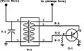
From Mark:
(Click here for a detailed view.)
I drew this up after removing and disassembling the one out of my '63 Imperial. It's probably the same for '61 to '63 Imperials, and '60 to '62 Chryslers. I'm not sure about the '66-'67 Charger, but, probably the same for them, too. (And '60 Imperials? I have no idea....)
From Dick:
It appears that the original capacitor was a .068 mfd rated at 330 VAC. I would suggest a replacement be the same value (sets the frequency of oscillation) but of Mylar or polystyrene construction, and rated at least 600V. The original transistor was a germanium PNP in a TO-3 case, which will be a bear to find. I have suggested to Mark that he try a MJ2955 as a replacement (Radio Shack part number 276-2043 at $1.99), but it will be necessary to adjust the bias resistor from 50 ohms to 120 ohms to accommodate the Silicon replacement.
Tip from Tony on how to troubleshoot electrical problems with these dashes:
When I couldn't find out where the flickering of my Electroluminescent dash lights was coming from, the way I repaired it was to disconnect every single dash-electrical connector (tagging the ones that aren't tagged already, for easy re-connecting), pull the wiring-harness under the dash, and unwrap the harness. I then carefully found where there could be short-circuits that I hadn't spotted before. I found a few nasty surprises, and repaired them with top-quality soldering and shrink-wrap insulation.
I came to this decision because I recently pulled out my '61 Imperial shop-manual wiring-diagrams, photocopied them and went at the copies with colored markers, tracing every possible connector for the 200-volt Panelescent dash-lighting system. Using a checklist, I disconnected every single white-wire-with-red-plastic-connector leading to an Electroluminescent ceramic light-source:
- Transmission-button light-panel
- Heater-A/C button panel
- Radio
- Clock
- Dash-Cluster & individual meters
- Windshield-Wiper-Switch Light
- Headlight-Switch Light
- Auto-Pilot-Switch Light
- Ignition-Switch LightEven after disconnecting these, the multimeter (set to test resistance) found a perfect short-circuit to the car's chassis. This would explain why:
- The dash-lights worked intermittently, failing utterly for no reason, despite CAREFUL, hours-long testing and diagnosis. One minute, nothing would work, then the dash-lights would work (with my meter indicating infinite resistance between the circuit and ground), then fail again, showing a short-circuit on my meter. The only thing that would change in between was my act of gently moving the wiring-harness an inch or so.
- The headlights are pulsing at acceleration - According to what I was told, the voltage-regulator is overloading because of the short-circuit in the system.
Tips from Tony on fixing a broken wire within these dashes:
1. In order to replace a broken or corroded contact it is first necessary to expose the edges of the foil conductive layer. This can be done by grinding away a small patch of the outer white protective shell about 1/4" to 1/2" from the edge of the panel (I used a Dremel multi-tool). Stop grinding as soon as the blue E/L layer is exposed. In some cases, where the contact has broken off, this lower layer is already exposed.
2. Using conductive paint, paint the exposed patch and a small surrounding area of the outer layer. (Conductive paint should be available from Radio Shack or a similar electronics outlet).
3. Using a thin plastic strip or insulating tape, cover the steel backing plate on the opposite side of the painted patch. It is best to fold the plastic just over the edge of the panel to avoid any possibility of a short.
4a. Solder the white wire from the power pack to a small speed nut. and slide the nut over the painted patch. Ensure that the part of the speed nut under the panel is fully isolated from the steel panel. This method is suitable for large E/L panels such as the '61-'63 transmission and heating control illumination panels.
4b. For smaller panels, Go through steps 1 & 2 and then, using either the original tag or any suitable metal contact, hold the tag firmly in place within the painted patch ( a pair of needle nose pliers are handy), and use rapid setting epoxy resin to fasten it firmly to the panel.
I have used both methods on my own E/L dash and the results have been very satisfactory.
Tips from Eric:
Corrosion in the EL connector rivet on the back of gauge keeps the EL connection from making contact. Copper wire to indicator needle degrades into a verdigris strand of nothing. Loop in EL needle wire keeps the wire from affecting tension on needle's motion. Instrument cluster voltage regulator really will melt together and fry the connecting wire.
Question from Paul:
I am going to call on the IML to see if any of you electro-luminescent lighting gurus can tell me what has happened. If not, that is okay too. My Imperial and I have a special relationship and things like this happen from time to time. It usually means that my car is smiling at me.
Reply from Tony:
You may have a hair-line crack in the EL coating on the needle.
Question from Gary:
I have read the repair and diagnosis for the power module for the electroluminescent dash, but I cannot find the switching transistor anywhere. The original is "Bendix PS20" and the suggested replacement is "MJ2955 (Radio Shack 276-2043)". The original transistor was a germanium PNP in a TO-3 case. Radio Shack has become useless for electronic components and they know nothing about this part Does anyone have the "specifications" for this transistor, so maybe I can find another replacement.
Replies:
From Dick:
MJ2955 is a Motorola number - you can buy these from your local electronic parts supply house, but there may be a minimum order size. Note that this replacement is a Silicon transistor, thus the bias resistor has to be changed.
I found it in the Radio Shack catalog, but perhaps it is not in the current issue. I just did a Google search on it, and came up with 548 hits on that number, one of which was the 276-2043 in the Tandy corp. site (Radio Shack). But there are many other sources listed. You just need to track one of them down - it might take a few phone calls. It is a Motorola product, one of the most vigorous companies in the semiconductor industry.
Another hit was on: http://www.onsemi.com/productSummary/0,4317,MJ2955,00.html
They have the MJ2955 in stock for $1.22 apiece, but there is probably a minimum order quantity - you'll have to contact them to find out what that is. Maybe you can buy the minimum quantity, then make the extra transistors available to others.
From Kevin:
If you go to www.newark.com (electronic components distributor, kind of like DigiKey) you can do a quick search for MJ2955, which they recognize.
Unfortunately, the on-hand quantity is 0, and the lead-time is 15-90 days. Which in this economy may mean they can't actually get them. I did not attempt to order any, but you might.
From John:
Give MCM Electronics a try. The company I work for buys a lot of electronic components from them. Also, member Dave Brown has had some experience repairing these. Perhaps he can point you to a parts source.
From Mikey:
I believe the NEWARK company catalog has those parts, they are a very large national supplier of electronic components. I was looking for the capacitor for the EL power supply, as the local Radio Shack droids only knew what their computer told them, and NONE of the folks in the local stores here are of the electrical/electronic tinkerer and inventor types that Radio Shack was once known for. I believe that unless you can find someone who actually knows what a transistor or a capacitor is and does, all youll find at Radio Shack will be a blank stare. Not to fault them as an entity, just a sign of the times.
Question from Tony:
I have spent today tinkering with my dash lights and I now have a fine glowing "Juke Box" dash. The only things left to fix are the push button selectors and the heater controls. Due to the way they are shoe-horned into the vertical pods on either side of the dash display I can't tell if they are also panelescent or if they use regular bulbs. Does any one know, and if they have bulbs how do you access them?
Replies:
From Dietmar:
On my 60 these fiberglass sticks work with one bulb for each unit one for the trans one for the a/c they are installed on top of each unit and accessible by removing the speedo-and tacho unit.
From Carmine:
They are Electroluminescent. They work on a "fiber optic" principle, meaning the clear plastic buttons are located next to an Electroluminescent panel. The glowing panel illuminates the buttons.
Question from Rex (1960):
I recently acquired a lovely 1960 Imperial and am enjoying getting acquainted with its many differences from my 1959 Crown. I love the configuration of the dash and the soft glow of the panelescent lighting. All of the dash and instruments light up, but the speedometer needle does not glow, making it difficult to see how fast one is driving at night. I am thinking this needle should illuminate like the other needles. Does anyone have a suggestion about this? I am also hearing a "shorting" sound when I try to adjust the brightness of the illumination which concerns me a bit.
Replies:
From Frank:
You may have a broken lead wire to the needle. I was able to get all the needles lit on my 61 by pulling the instrument cluster and soldering the lead. If you do this be sure to disconnect the power first. There is power pack with capacitor and the voltage gets high, about 250V . Its low amps but 250v still has a little bite to it.
From Paul:
It is also possible to repair the broken lead to the speedometer and other gauge needles with conductive glue. The product for this is called Vigor Circuit Maker CE-890. It is made for repairing quartz analog and digital watch circuitry. I ordered it from a watch repair material supply house. You may be able to order it through your local jeweler.
There is also a product in the field and available at many auto parts stores for reconnecting breaks in the rear defrost systems on modern cars. I have not tried this product so I can not say much, but it sounds like it would have to be similar to the product that I use.
This product eliminates the need for the use of heat or a soldering iron which can be risky. The product dries very quickly and provides a strong repair. I did not have good luck using heat on these delicate parts. Perhaps it is my inexperience, although I did build a color T.V. from a kit in 1972, but the wires to the needles in our systems are very thin. If you are careful, I suppose that since the wire is so thin that it would heat quickly and flow the solder easily, but I didn't have a good experience with it.
As far as the noises that you hear, I can safely say that if there was a short in the system, the lighting would not work at all. It is common for the lights to flicker a little bit when adjusting the brightness, and may have a corresponding clicking sound emanating from the rheostat in the headlight switch. Some of my cars do this and some of them are smooth, but I have not attempted a repair. If they work, I normally leave them alone.
As a rule, I generally find an acceptable level of brightness that suits me and tend to leave the switch alone. Although, as with all rheostat type switches, it is probably helpful to turn it once in awhile to keep the contacts clean.
If there is a short in the system, the entire system will go dark. If there is an open circuit, only the one that is open will not be lighted. The way to find the short is to disconnect each light one at a time and reconnect it until the other lights come on.
The only lights that I have ever had short out were the labels for the switches, so if I have a problem, I start with them, but any of them can short out. The ignition switch light has been the culprit more than once.
From Tony:
One further possible cause is a hair-line crack in the E.L. coating on the needle. You may need a magnifying glass to see it. I have had this problem on the hour hand of my clock..
Question from Allan (1962):
Does anyone know where the power supply for the dash is located and what the output voltage is supposed to be? Is it the cycles per second or the output voltage that changes. The shop manual just says 200 volts and 250 cps in the radio diagram, nothing about what controls it.
Replies:
From John S.:
The power supply for the dash is located above the drivers side kick panel. This may not be the problem with the dash lights. Often, one of the components shorts & causes the whole dash to go out. Disconnecting the offending item or items will restore the rest of the lighting. I've had a lot of these cars & a lot of practice making the dash lights work.
From John B.:
The EL "black box" is an oscillator. The output voltage varies with the input (battery) voltage that is adjusted by the dimmer knob on the dash. The high voltage output is an AC voltage. I took one of these to work years ago and did a little bench testing: I measured a whopping 790 Volts peak-to-peak with a frequency of 294 Hz (an AC voltmeter will give reading of about a third of this -- around 250 Volts RMS). The oscillator is pretty crude and the circuit suffers from the aging of a capacitor (it gets leaky and loads down and finally shorts the high voltage output) but the EL dash is pretty darned high tech even by today's standards!
Question from Canu (1962):
When I turn the head-lights on, the dash lights are strong and bright. As the minutes go by, the dash lights fade to almost nothing. The headlights nor the running of the engine seem to be affected by this phenomenon. If the dash lights are then turned off for several minutes, once turned on again the cycle repeats itself. What's the simple fix and cheap repair?
Reply from John:
The power pack is getting weak. Check our vendors list for a good rebuilder.
Question from Paul (1962):
I have a question regarding the lights on my dashboard. Under the speedometer, were the individual gauges each are displayed, at night, when the headlights are on and therefore so are the dash lights, each block of the dash is lit in a funky green glow.....but a couple of the orange needles are lit....and two of them are not. I don't understand this as the blocks are well light...but the needles are not. And I can't tell where the needle is....I guess I think if the block is lit, then the needle should be. Can anyone explain this and any recommendations on a repair person?
Replies:
From Brett:
Essentially, there are no light bulbs in the dash of your car. There is a power converter that converts the 12v. DC power to high-voltage AC current. This current (the white wires under the dash) causes the phosphorous coated parts of the panel to glow. There are long, thin rods inside your instrument cluster that glow and very, very thin wires that attach to the gauge needles. Typically, the wires become brittle and break. (Except for the ammeter, which gets its power through the gauge stem) This is a specialized lighting system that was developed by Chrysler and Sylvania. It has it's quirks. So, I would not recommend taking your dash cluster to the local electronics shop, they are likely to not want anything to do with it or charge you $60+ an hour to fiddle with something they've never seen before.
I'd recommend sending your cluster to one of the shops listed on the web site. They're all familiar with the "EL" system and can properly connect power to your needles... they'll usually give the needles a fresh coat of orange paint as well.... All for probably much less than a local repair shop would charge. I sent my '61 unit to Don Steger in Sacramento, CA (916) 929-8274. I chose Don because he ran a regular repair shop that was open regular business hours. (Editor's Note: Don is a member of the Imperial Owners Association of Sacramento Valley and has twice given repair seminars at statewide Imperial meets.) The others listed as "EL" repair technicians didn't answer their phones at reasonable times when I was in the market.
From PEN:
You have Electroluminescent dash lights. They glow. They work by applying a voltage to a phosphorescent substrate, usually in layers. All the gauges, radio, pushbuttons, speedometer, etc., are intended to glow when the lights are on. The device that causes this is a power pack located up under the left kick panel. The wires for the system will be white, 22 gauge or perhaps a little bigger.
The needles on your gauges are supposed to glow too. If some don't, then look for a really tiny little wire in each gauge that has broken off from the needle. You may reattach it with electrical solder, and a precision solder iron. This is one of the really cool things about these cars. By the way, is your convertible a light gray with black dash?
From Jay:
I have had success with getting everything working in our '62's dash lighting system. I got lucky as there were no shorted EL panels to troubleshoot. The hardest part was resoldering that little microscopic (and insulated no less) litz-wire that powers the illumination of the four gauge needles. If you don't have good eyes, a steady hand, a low wattage soldering iron and a lot of patience, send the gauge to the professionals. I believe that the pros charge about $25-35 a gauge to completely disassemble and restore them to their original glory.
Brett, you are right for the most part. The '61-'62 Imperials have no light bulbs in their dash "cluster" with the exception of the "high-beam indicator" and the "parking brake warning". The bulbs "outside" of the dash cluster are turn-signal indicators, map light, glove box light and sometimes an ash-tray light.
Transmission and climate control push-buttons should illuminate using the EL system, but don't expect to see the radio's pushbuttons. They are not designed to illuminate.
Question from Steve (1962):
The dash went dark this evening on my 62 convertible. I have replaced 1 power pack and repaired another during my 2 years of owning this car. Recently I have had to work the headlight switch a couple of times to get the dash to light. This evening while driving this did not work.
Any suggestions? Is there a way to troubleshoot whether it is a ground, headlight switch, or power pack. That pack is a devil to get out if not the actual problem.
Reply from Brooks:
I think this sounds more like a problem with the rheostat in the headlight switch. Don't have my shop manual right here handy, but there is a wire (seems like it's a pair?) going as 12-volt input to the power pack. Apply 12 volts directly to the 12 volt input (bypassing the headlight switch) and see if the dash lights up. If so, voila!
Question from David (1963):
I have been told that you should not ground the sender wire to see if the gauge works. Is this correct or not and if so how does one check these gauges? I put in a "new" sender unit which briefly gave a 3/4 reading before slowly dying as did the previous gauge?
Reply from Dick:
The electroluminescent system operates the illumination of the display of information on the gauges, not the innards of the dash gauges themselves.
The testing methods are not affected by the type of display illumination, and our previous statements are still in effect. Grounding the tank or other sending unit wires for a few seconds will not hurt anything -just don't leave it grounded with the key on for more than a few seconds. This is to see if the display unit goes to full scale - if it does, your gauge unit and regulator are fine. If it doesn't, you know where to look for the cause (behind the dash instruments).
If you make contact with the 250 volt AC terminals while poking about behind the dash units, you are likely to regret it!
Question from Eric (1963):
Ah, the wonderment of figuring out what some past person has done, an automotive CSI in the making here. I removed the instrument cluster in my recently acquired '63 Crown Four-Door to find a couple of unusual items.
There is a condenser shaped and sized device that was in a holder that was mounted behind the right nut holding the clock in. This condenser has a black female connector on the end of it. The FSM instrument cluster page doesn't come thru very clearly, but I don't show mention of any condenser to the temp gauge. I'm picturing this condenser connecting to the dual tanged connector on the back of the temp gauge. This deduction comes from the fact that there is a black wire on that 2nd tang w/what looks like a non-original connector. This apparent newly installed wire goes to nothing else, dead ending w/a similar newer connector end. Is it likely someone was attempting to revive a temp gauge, not realizing this condenser was unplugged?
The wiring harness to the 2 right gauges has a red wire cut at the end of the harness tape wrapping. Being the FSM instrument cluster page isn't copied as clearly as the other pages, I can't quite make out where this wire goes yet, still working on tracing this down. There is also a very thin black strand of rubber hose in this harness that seems to be cut off. Maybe this is a wire tracer?
In a spare instrument cluster I have partially apart, there are a few small rubber holders or spacers. They are small squares blocks w/a channel thru them. It looks like they could hold in the EL sticks or be a spacer of some sort. Also, a rectangular strip of rubber came out of the assembly, about 3/4x1''. This cluster had been apart before and these parts loose in the unit, I think. This was my 1st opening of one of these, not sure where these 2 different items are placed.
Replies:
From John:
I had something like that done to a 63 I owned back in the early 70's. I knew it was to make the gauges work, but now I understand about the built in one in the temp gauge. I managed to fix one on another 63 I owned.
From Paul:
I found a similar condenser behind the the cluster in my '63 also. It wasn't connected to anything so I removed it and put it in the glove compartment. I have had ten or more of those apart and never run across that part before. Mine was mounted the same way as yours. I have added a separate voltage regulator and by passed the one on the temperature gauge since it goes bad suddenly and fries the gauges. I had guessed that the condenser that you described was used to somehow remedy the bad built in voltage regulator but I don't know. I can report that all instruments and clock are working perfectly without it.
The little rubber blocks are spacers and insulators for the plastic lens that contains the numbers for the speedometer. I believe that they also hold the EL lighting tubes (that light that same lens) in place as you suggest.
The thin piece of rubber tubing doesn't sound familiar, although it may be an insulator for the wires to those same EL tubes inside the cast metal housing to keep them from grounding out.
Mikey with the '62 described everything that I know about the red wires to a tee. I would be happy to yank my cluster and tell you anything that you need to know, but I am waiting for a new speedometer cable before I do that again since I damaged mine the last time I had the cluster out (or maybe it was already damaged) and had one H of a time getting the speedometer to work again after reassembly. The red wires with the eye connectors go to the ammeter posts, and the red wire with the plug goes to the voltage input for the power to the gauges on the temperature gauge or the by pass regulator if you have one. All of the wires for the EL are white with red connectors, and there is a black jumper wire from the temperature gauge to the power side of each of the others. The sending unit wires are gray and purple.
This page last updated December 1, 2004. Send us your feedback, and come join the Imperial Mailing List - Online Car Club