
There is a lot of information out there on electroluminescence in terms of theory and applications. But there is little out there on how all this applies to our Imperials. So for the sake of this article, the instruments from the 61-63 Imperials will be used.

Here are some things to keep in mind about the operation of this lighting system:
- Input voltage - 12VDC
- Input Current - 800mA (for the entire system load including the radio)
- Output voltage - 280-300VAC
- Output current - 1-2mA
- Frequency - 120 - 200 Hz.
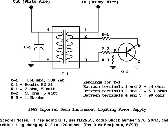
There is a very good schematic from Mark and Dick Benjamin that shows the basic components of the EL power supply. For those of you with 61-63 Imperials, the power supply is located above the driver's side kick panel, behind the parking brake mechanism. You won't be able to miss it with the ubiquitous transistor case facing you. Repairing this unit is feasible as long as the transformer is in good shape. If there is a problem with the transformer, then that's where things get difficult, as transformers are purpose built. For something like this application, they are not easy to find off the shelf.
So that leads to a "what if" that came to mind. What if there is an Imperialist out there with perfectly good gauges, but a damaged transformer? Is there a way to bring back the lights? I started pondering this question, and one day at a local cruise in, it dawned on me. I was looking at someone's Camaro whose engine compartment was wired from stem to sternum in neon lights. These lights work on the same principle, and they also require a 12 volt power supply. So the next day, I went to the local auto parts store and started looking at these neon kits. There are many kinds, and they come in many colors and sizes. I bought the cheapest one I could find for my experiment, and set it up on my workbench.

As it turns out, this little unit is perfect for lighting up a single gauge for testing / restoration purposes. If you want something to totally replace the power supply under your dash, I recommend the units that drive several neon tubes. These run in the $80 - $100 range, but their power supplies are better suited for the load. They are also better enclosed with heatsinks, so that you will have more longevity out of them.
The Red Plug
You will notice that the gauge cluster as well as the radio, each has a white wire with a red plug on it. This is for the EL power. Like all other electrical circuits in your car, chassis ground is the reference for EL also.
Every gauge will have its own connector for EL power. On this view, it is the spade shaped lug at the bottom left of the gauge back. The other bolts accommodate the gauge's wiring from its appropriate transducer. (i.e. fuel level, oil pressure switch, etc.)

You will also notice from this view, that the convention of the white wire for EL power continues on to the gauge face as well as the needle.

The gauge needles, and the light sources for other parts of the instrument cluster, are fine glass tubes that have the EL material and electrodes inside them. Think of them as tiny neon tubes. Look closely at the very first illustration showing the front face of the gauge cluster by clicking on it. You will see the tubes rest inside pockets that are molded in the plastic. This is what allows for that cool blue/green glow that you see emanating from the entire instrument face.
The images below will show you what these tubes look like up close. On this image below, look at the tube at the bottom left of the gauge cluster.

The image below shows a closer image of a typical tube. Notice the coil of wire at the bottom of it making contact to the black stuff on the plastic case. This is the tube's ground wire. The white wire like in the EL convention, is the "hot" wire. In case you are wondering, the black stuff is a conductive paint that allows a better ground connection to be transferred to the coiled wire. This is a redundancy, since the ground lead on these tubes is bent in such a way that it makes contact with the metal bezel of the gauge cluster.

The backside of the plastic bezel also carries tubes to light up the odometer and speedometer.

There are two details to keep in mind during the disassembly of a 61-63 gauge cluster. The metal bezel has these small rubber grommets to help make a good tight and vibration free seal to the plastic. The illustrations below show what they look like and how they are installed.


Another detail that I am not showing here is the use of masking tape (or some kind of paper tape) that was used at the factory to hold the tubes in place at their very tips on the plastic bezel. After 45 plus years, you can imagine how brittle the stuff becomes. But without taping these to the plastic bezel, the job of putting the whole thing back together will be a frustrating disaster. (If anyone ever doubts that this vintage of Imperials was not hand made, just show them this part...)
The Gauges
The gauges are pretty amazing when you think about it. The face (and this applies to the radio too) is simply a mask that covers and entire square or rectangular area of EL material. Wherever there is a number or a tick mark, that's where the EL material is exposed.


The gauge needles are tubes too, that get painted with a coat of phosphorescent red paint. So essentially, the gauge needle is a light tube, and when lighted, this excites the particles in the red paint to give off that cool reddish glow we all admire...

Notice on the close up image of a typical needle, that the needle itself is a tube as mentioned before, with a coat of red phosphorescent paint on it. When you look at the close up image, you will see that I purposely peeled off a little bit of the paint to illustrate this. The needles have counter weights on the opposite side, which are small magnets. Notice how the ground lead is coiled and then connects to the needle's frame. Notice also the axle that the needle pivots on. This is an insulated piece, where one axle is ground (facing you), and the other one is hot (EL). The small insulated red wire is the hot wire, and it connects to the other side of the axle. There is a white wire that will solder from the EL lug in the gauge to the housing where the needle pivots.
The gauge needles are not the only area to be treated to phosphorescent paint. On the faceplate, we have the tick marks and fonts for the speedometer, etc. These are painted in a white phosphorescent paint in order to give off the appropriate glow also.