|
|
Imperial Home Page -> Repair -> Electrical System -> Charging System
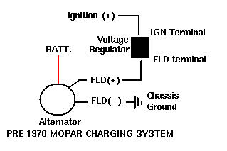
Diagram #1 shows the basics of the early alternator / voltage regulator (VR) design. There are 2 brushes in the alternator, each one has a field terminal, one is labeled "FLD", the other is labeled "GND". The GND brush is grounded with the brush mounting screw. the other brush is the (+) brush (or field) and attached to it is a green wire that routes over to the Voltage regulator (which is behind or near the brake master cylinder) this green wire is connected at the voltage regulator at the "FLD" connection (with a screw). The other connection on the Voltage Regulator is a blue wire with a female plug end. This is the "IGN" Ignition side.
Basically, the Voltage Regulator completes the charging circuit and allows the alternator to charge the system. When a certain voltage is obtained, the regulator "opens" (or turns off) the circuit until the electrical system's voltage drops, then it completes the circuit again. The old Voltage Regulators are repairable and rebuildable. The 1969 Dodge Shop manual (available from a number of vendors, including Year One) details how to do this. If you think your regulator is failing, open it up and clean the "points" with some emory paper (sometimes these points get corroded).
NOTE: in diagram #1, the FLD is generally green, and the IGN wire is Dark blue on stock wirinig harnesses.
 |
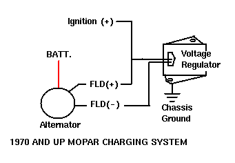
Mopar Charging System, 1970 and up
In 1970 Mopar switched from an analog type voltage regulator to a transistorized regualtor. The basic circuit is completely different. Before the voltage regulator monitored the (+) ignition voltage and opened/closed the (+) Field circuit as needed to maintain a steady voltage. The 1970 design, instead, monitored the (+) field voltage and open/closed the (-) ground field as needed to maintain a steady voltage.
 |
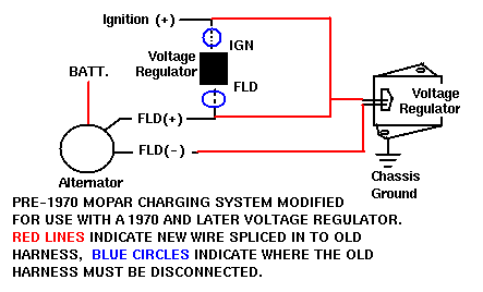
Early Charging System modified for use with a 70 style VR
There are a number of reasons one might want to upgrade a per-1970 system to a transistorized voltage regulator. The list of reason include
Below is a diagram describing how to install a 70 and later Voltage Regulator on a sixties mopar.
Question from Bill:
My battery will not hold a charge overnight. Is there a drain somewhere or something else I should be looking for?
Reply from Norm:
If you have tried all other avenues without success, don't forget to look at the battery itself. I would take the battery back to where you purchased it and return it. The battery may be defective and not charging properly.
Diagram 3
Basically, a wire is added to the second Field brush on the alternator. On the original alternator, this brush is grounded to the case of the alternator, so you'll need to either change the alternator to a 1970 or new style, or adapter the newer brush set to the old alternator (I've never done this, however, from looking at the brushes, it looks do-able. The brush set costs about $3). The second field wire is connected to the outside plug on the newer VR (two plugs, one is in the middle, one is on the outside). The original field wire that ran to the "FLD" plug on the original VR (green wire) needs to be connected with the wire that ran to the "IGN" side of the original VR. This wire (both the old FLD and the old IGN) need to be connected to the center plug on the newer VR as well. One more important step is required, the new VR must have a good ground (-) signal to its case. Mount the new VR to a fender or the firewall and be sure to scratch the paint off of the fender and the case so a good ground is insured. If there isn't a good ground to the new VR case, the charging system will not work.
This page last updated September 1, 2001. Send us your feedback, and come join the Imperial Mailing List - Online Car Club