Imperial Home Page -> Repair -> Engine -> Rebuild
"The end result should be a freshly sealed, non-leaking, smooth-as-glass engine that will look and feel like new, while bypassing cylinder boring and replacement, which can double or triple your expenses."
-By Kenyon Wills
|
An engine�s seals and inner workings all wear and fail at different rates. The Big Block Chrysler RB engines (413, 440, 400) all develop bad seals with age and leak, and they wear out piston rings long before they stop working. Catastrophic failure of the bottom end is uncommon. When you take your engine to a machine shop, and say �I want this rebuilt�, to the machine shop it means that the engine must be made completely new in such a way that they will not be held liable for any complaints or problems, so they will replace everything and give you a top of the line solution, which is technically the most accurate solution possible. They will also make their speedboat payment for the next few months after you�re gone. Here is how to do a ring and valve job on an older, running engine. If your engine isn�t running due to internal failure, that�s another subject. This description is designed to get you through on the cheap. It�s written from memory and not as I do it, so there may be some additional steps for you to watch for, but I promise to cover the basics. This paper presumes that you have a complete set of deep and shallow sockets, and other basic hand tools. It also presumes that when you come to a point where you are not in possession of a needed tool, you will go buy it, since it is a renewable resource in comparison to a mechanic�s service fee of $95 an hour.
"Preparation and Supplies"BEFORE YOU START: Get an engine hoist, an engine sling, and an engine stand. These tools are only needed for doing engines. Start trolling craigslist TOOLS section and try to score a complete set. $125 is maximum, and patience may yield better. You can often rent these three things very cheaply at the local tool rent place. Really cheap, so check that one out too if you would prefer not to possess and store them. Get a service manual if you don�t have one. It is REQUIRED for success. Check your toolbox for a deep, 12-point 3/8� socket. Go buy one and keep the receipt in case you don�t need it. Expect only a high-quality version from Snap-on or SK or something. The 12-point requirement means that the metal must be high quality, and it�s an oddball request, so only the better lines have this particular tool. Get it before you begin. Seek out K&W COPPER COAT goo, 16 oz can. I found it on the shelf of my local non-chain store, so you�re on your own locally, but google shows it here and other places (but this has a good image): http://www.amazon.com/Copper-Gasket-Compound-liquid-dauber/dp/B00030BFKG This product works best if you coat the two surfaces to be gasketed, and then coat the gasket on both sides, getting the gasket wet and allowing the gasket to absorb the sealant so that it is �wet� � THIS IS IMPORTANT � Don�t just we the two mating surfaces � the rest of this essay assumes that you know this when it says to use the sealant. Get a tube of �Hi Temp RTV Silicone� gasket material from the auto parts store. Probably in a metal tube with a clear plastic cake-decorating nose on it. I like black for reasons that I can�t recall. A large hydraulic floor jack and at least two jackstands. Before I bought a lift for my garage, I used four because I like the car level when I�m working on it from underneath, personally. Get a piston ring compressor tool. The pistons are about 3.5�-4� in diameter, so get one of the �larger� ones and not something for a small foreign car. Be sure that you own or can borrow a torque wrench that is good for up to 90 foot pounds. Go on ebay and get a set of 12 �valve cover studs� with nuts. Don�t go crazy � shop for price, and get ones that have minimal un-threaded areas and are relatively short � you don�t need anything fancy or long. ARP or Moroso are two known brands. Do not get the $100 stainless steel ones unless you are a fool who wants to be parted with his money. About $20+ ought to do it.
Shop for CALYX Manifold Dressing. Small black plastic can. I got mine from Eastwood. It�s buried in their catalog, but it�s good stuff.
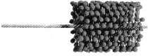
Go online and order an engine cylinder hone after you�ve checked and made sure that the rental place does not have one. This is a good tool to borrow or rent if possible. I use one that I call the �dingleberry� version. It looks like a giant lollipop with lots of little balls on wires in a cylindrical shape. You want to source this in advance so that you�re not paying top dollar the day that you need it. There are other hones out there with 3 straight arms and stones in them. Skip them. They�re not as much fun to use, and I think that this one does a better job.
"Engine parts to source"(shop online first � ebay then Rockauto.com)1. Complete engine gasket kit. 2. Intake manifold gasket pan. 3. Carburetor � new or rebuild your existing unit 4. Oil temp sender(s) 5. Water temp sender 6. Water pump 7. Fuel pump 8. Oil pump 9. Rebuilt alternator 10. Voltage regulator 11. Positive and negative battery cables � you may need to measure your existing ones to get right length. 12. Battery? 13. Rebuilt power steering pump 14. NEW power steering pump pressure & return lines IMPORTANT IMPORTANT IMPORTANT! 15. Starter motor (important- they�re cheap and the heat from the exhaust wears them out � do this!) 16. Fan belts (x4) 17. Thermostat 18. Upper & lower radiator hoses & hose clamps 19. 6� of fuel line & hose clamps 20. 4� of vacuum line (to brake booster) 21. Spark plugs 22. Spark plug wires 23. Distributor cap 24. Distributor rotor & points 25. Electronic ignition conversion kit � if desired. I like Mopar, and they have a kit (mount the electronic module in front of the radiator on the radiator support to keep it cool is my advice). 26. Recore/flush/rod radiator 27. Case of 20-50w oil 28. Air cleaner filter 29. 3/8� 12-point socket, deep 30. Calyx Manifold Dressing 31. Valve cover studs & bolts (x 12) 32. K&W Copper Coat Sealant 33. Hi Temp silicone gasket maker 34. Piston ring compressor 35. Cylinder hone 36. Torque wrench 37. Factory Service Manual 38. Hand cleaner 39. Rags 40. Engine stand/lift/sling/jackstands 41. Bench grinder with medium or fine wire wheel 42. Oil pressure sensor socket (Get the sensor first and then ask the parts store for a socket to fit it � most places should have this automotive-only tool) You are an idiot by human nature, so wind black electrical tape around the socket to set it apart from the rest of your sockets � it ought not be used for other purposes and is special. The tape is a reminder.
"Engine Bay Preparation for Removal"1. Remove the hood from the car. Get a thick moving blanket and lay the hood on the roof of your car unless you have a convertible. 2. Drain the oil out of the engine. 3. Drain the coolant out of the radiator. There is a small fitting down on the bottom that looks like a propeller the diameter of a US quarter. Use pliers to GENTLY twist it open. It is a spigot and will allow you to drain the radiator without removing the big hoses and making a mess. 4. Remove the battery and the air cleaner. Set battery on wood and not concrete so that it does not discharge. 5. Look at the engine that is in the car. There are no exotic tools needed to take it apart with two exceptions, and they�re not that big of a deal anyway. 6. Make a decision whether the transmission is coming out with the engine, or if it will remain behind. This is important. The reason to pull it with the engine, is to drop it off at the transmission place for rebuilding. Around here, the 1962 and later trans will come back with a new torque convertor and the rest fully rebuilt for about $700. Shop around. You want someone you can trust who speaks English and preferably has gray hair. They�re easy to rebuild, but also easy to rebuild wrong. Ask for the �Heavy Duty� clutch packs � they can come (I think) with either three clutches or four, and you want the one with four if offered it. Do not get a shift kit or anything else if you want your car to shift smoothly and without slams. 7. Transmission coming out? Start at the back and remove everything that�s attaching it to the car. This process will vary. Some early cars require that you remove the cross-member that it sits on, later ones don�t. Inspect where the driveshaft meets the trans. If there is a flange or brake drum, remove bolts. If not, then the driveshaft slides in and will remain behind without fuss. Everything must be disconnected, including shift linkages and transmission fluid lines. Disconnect the driveshaft from the trans if it�s bolted on. If not, it will slip out as you pull the engine, no tools required. 8. Transmission staying? Remove the plate that covers the forward bottom of the transmission in the large bell-shaped front thing called the bell housing. 4 bolts. 9. You will now see a large sprocket. For 1963 and later, unbolt the 4 bolts on the forward facing vertical surface that hold it to the engine. These bolts are at the four points of the compass and the engine�s crank will need to be rotated to get them to the lower portion where you can get a wrench on them. Use a large screwdriver to pry against the teeth and spin the crank to get to number 2, 3, and 4. 10. Locate the motor mount bolts. The motor contacts the frame of the car. There are large bolts that go through each of the two points of contact (at the bottom). Remove these � the motor mounts will come out with the car later. 11. Get two wratcheting tie straps if the trans will stay. Run one or both of them under the front of the transmission just ahead of the trans oil pan. They can go out and around the torsion bars. Tighten them tight. They will support your transmission when you remove the engine, which is currently holding the trans in place because they�re bolted together and act as one unit. 12. Disconnect the steel tube exhaust pipes from the cast-iron exhaust manifolds. Bolts will be rusty and may snap. This is OK, you will want to replace them with new grade 8 fine-thread bolts from the hardware store during reassembly anyway. They may not want to come apart. Use penetrating oil, and deep six point socket so as not to strip it using a 12-point. Cut with die grinder or by any means needed � they gotta come off. 13. Go up on top and remove the carburetor and get it�s linkages loose and flopped off to the side. Photo the entire engine compartment and check your pictures for clarity now, since you may need them to remind yourself later. If you take more than a month to do this process, you�ll forget how it all went together, so don�t lag. 14. Remove the fan belts. 15. Remove the fan and clutch from the front of the engine. 16. Remove the fan shroud. 17. Remove the radiator 18. Disconnect the fuel line where it connects to the fuel pump from the frame. Cut it with Dykes, since it MUST be replaced. They are always old and nasty and are a potential problem later and we�re doing this right the first time here. 19. The spinning accessories are coming off either here or once it�s out. I leave them on, but it probably doesn�t matter. 20. Remove the carburetor. 21. Remove the starter 22. Consider that the AC compressor, if disconnected from its hoses will need the system reloaded. Some lazy people will unbolt it and try to flop it back and to the passenger side firewall to move the hoses and compressor out of the way. Do as you see fit, but be careful with the hoses � they are probably brittle from age and thermal cycling� 23. You have a safe, secure area for these parts where they won�t get stepped on. Put them there as you go and keep your work area clean. 24. Mentally/viduslly/physically run your hands over the entire engine and look for other things that can be disconnected. Wiring harness, especially. Use masking tape and a pen to mark where things go AND take pictures so that you don�t rewire things backwards later. DO THIS! 25. Engine is now disconnected from the car in all ways, but still sitting in there. 26. Transmission is either supported at the front by tie-straps or is similarly disconnected from the car.
ENGINE REMOVAL1. The intake manifold atop the engine is held on with 8 bolts. Remove two at diagonally opposite ends and then reinsert them with the engine sling�s ends secured to the engine. This is how the engine hoist will be connected to the engine for lifting. 2. No trans removal: lift engine up slightly with sling centered above the (now empty) carb location. Insert a pry bar between the engine and transmission and/or rock the engine using your hands. This will separate the engine from the transmission and allow it to be lifted up. You may have to lift a little to clear the engine motor mounts from their cradles, and then move the engine forward to clear the firewall/heater housing. 3. Trans removal: Spin engine sling so that the hook point is to the rearmost setting, using the threaded adjuster that is in the sling. You want to move the lifting point as far back as possible, since the transmission is sticking out behind the engine and you want to come closer to balancing it rather than lifting from the front and having the tail drag/drop. 4. Lift engine vertically to get the mounts off the cradles and then slide the engine forward. Watch for wires or other things that you may have missed or not removed. 5. Pull the engine out of the car vertically if no trans attached. 6. With Trans attached, as the engine comes forward and up, use a speed wrench, or preferably an air wrench to spin the nut on the threaded engine sling to move the hook forward in the tool�s range of motion. Doing so will shift the point at which the engine is held forward, tipping the weight of the assembly backwards, and dropping the tailshaft of the transmission down. It wants to come out of there being held at a diagonal, while alternately lifting the engine up and scooting the engine hoist backwards away from the firewall. 7. Remove engine from car, being careful to leave plenty of clearance as it goes over the grille and onto the garage floor. 8. Remove transmission if still attached to engine. 9. Lift engine up and bolt the engine stand to engine securely.
Engine Tear-Down1. Take photos of engine from both sides, above and below. Engine stand allows one to rotate the HEAVY engine. Don�t rotate it until it�s stripped of all parts. 2. Take out your wrenches and remove every nut and bolt that you can find. The following pieces will need to come off, with all hardware going into a box for subsequent cleaning. 3. Remove From Engine: 4. All spinning accessories from front of engine. 5. Remove flex plate and/or torque convertor from rear. Put a sock in the convertor�s mouth to keep dirt out. 6. Engine sling and all 8 bolts holding intake manifold on. Use prybar to break it loose and then set it aside. 7. Valve covers. 8. Rocker arm assemblies from under valve covers, doing each of the 5 bolts a few turns at a time, evenly removing the pressure. Reinstall will be reverse. Don�t do one bolt at a time! 9. Pull rocker arm assy�s off and place in a box. Photo them so that you can see how they are arranged. 10. IMPORTANT: the pushrods and lifters are mated and should not be mixed up. I always keep the engine oriented in the garage in the same direction that it would be if in the car and parked there. Find a safe place where you can lay the pushrods and lifters out in the order that they were in the engine, and cover with a clean rag. Set atop a clean rag. When you return, you should be able to pick them up sequentially and install them as they were on the engine. If you take my advice and replace the cam, you�ll replace the lifters too, and it won�t matter. Cams and lifters wear together, and each cam lobe wants to return to its own lifter, so be careful if you�re chintzing and want to reuse these parts (presuming that the cam appears to be OK when you get to that). 11. Once the lifters are out, go to the back of the top of the motor and remove the oil pressure sending unit(s) that are screwed in at the back. There may be more than one, and the larger one will only accept a specific socket if you are a gentleman. A vise-grip may suffice, since you�ll be tossing both of them. You may need to rent an oil-pressure sending unit socket at the auto parts store � there is no other socket that will work, although there are one or two that will feel close. They�ll fail though � you need the right tool, and it�s a good thing to have in general, since it�s only money�.. But they can be borrowed or rented if needed. Keep the sending unit to compare to replacements to ensure that you have the right ones before installing. 12. Go to front of engine and pull the small plug that has a mushroom tip on it and a six-sided hex head. Remove this � it is the sensor that tells your temp gauge what�s happening inside of the water galleries hot or cold. 13. Remove the six bolts on each side of the engine which hold the exhaust manifolds on, and remove them. They may need to be gently pried loose, but probably not. 14. The heads are held on with a lot (16?) of bolts that you can now access in the absence of the rocker arm assy�s. Unbolt these bolts by cracking them loose first, starting from the outside and working in sequentially. It is important not to loosen or tighten them in random order in order to keep the whole thing from mildly distorting in the process. It need to be flat so as to sit squarely atop the engine block for a good seal. 15. Remove all bolts and add them to the bucket of other bolts that you already have � all hardware other than pushrods/lifters goes into this bucket for subsequent cleaning, and it can all be mixed/jumbled. 16. Once you have removed all bolts from one head. Try lifting it off the engine. If it does not come, use a screwdriver to gently break the seal. The head sits on the engine and will not slide off if you�re CAREFUL. There are two small locating pins that stick out of the top of the engine to keep it in place. Have your hip against the area where the exhaust manifold was in order to keep it from popping off and dropping onto the floor. BE CAREFUL. If it does pop off and drop, it can break your bones, so keep your stupid leg and foot out of the way and go slowly, working only one end or the other at a time. 17. If you want to be extra careful, you can pull the safety pin out of the engine stand and gently rotate each head so that it�s straight up and down, reducing the chances of it popping loose and sliding off. This is good to do if you have not been through this before. It�s an extra step if you know what you�re up against and act accordingly. 18. The heads are interchangeable, and each has a flat surface on one end with threaded holes in it. Stand the head on edge one the floor, out of the way where you won�t trip on it or bump into it. The smooth metal face that was touching the engine must not get banged or set atop anything. It is smooth and flat, and must not be damaged. You can lay them on cardboard on your truck bed for transport, but don�t allow them to slide around or get screwed up. You have been warned. 19. Repeat for the other head. 20. Remove the motor mounts. 21. Move to the front of the engine and use an extension to remove the 6 bolts from within the pulley and remove it. 22. There is now a large thick disc with a large bolt on it. Remove large bolt. 23. The large disc is the harmonic balancer, and must be pulled off. You will need a puller. Buy or rent. Two bolts go through the puller and into the now-empty threaded holes that the pulley bolts were in. The puller is threaded and turning it by hand with a wrench will gradually draw the harmonic balancer off the end of the crank. 24. Remove the water pump � it is the snout sticking out, and is held on with 4 bolts. Discard the water pump, keep the bolts. 25. Remove the bolts that hold the water pump housing/manifold onto the engine. It is gasketed on, and may be sticky. Pry it loose or hit it with a rubber mallet. DO NOT stick your stupid screwdriver in underneath it and gouge up the surfaces that are supposed to mate. Same goes for anything else that�s mated together. Gotta go back together and not be gouged up or no seal and you�ll be mad. 26. Remove the 8 bolts from the egg-shaped cover that is on the front of the engine, and gently pry that away from the engine. It is bolted in from the bottom, and those bolts hold the oil pan to the bottom of this stamped steel cover, so get those bolts out before removal is attempted. 27. Removing the timing chain cover reveals the timing chain. Remove the bolt in the center of the large sprocket, and then remove the sprocket and chain. Once the large sprocket and chain are off, you ought to be able to slide or gently pry the smaller sprocket off, but if it�s stubborn, leave it alone and point it out to the machinist for removal by him later. 28. Up at the top of the front of the engine is the hole that the distributor was in. It got removed earlier because it is in the �spinning parts� that were removed. Remove now if not already. 29. The distributor is driven by a sprocketed deal that�s sitting inside the front of the engine. Put your fingers/fingernails under the bottom edge of the teeth and lift straight up the hole that the distributor came from. It spins and has smooth polished surfaces on the shaft that�s under the teeth. Protect these surfaces from scratches � don�t jumble in with the rest of the hardware. 30. The top of the engine is now clear of all things which can be unbolted/removed. 31. The front of the engine is now clear of all accessories and is just a bare block. 32. It is also now far lighter without the heads, and is easier to spin in the engine stand, so rotate the engine so that it inverts. Expect some oil and coolant to spill out, so have rags there so that you�re not standing in or slipping on slippery flooring. 33. With the engine upside down, remove all oil pan bolts and then gently pry the oil pan off, taking care not to bend or warp the flange that�s mated to the engine � you�ll need this to re-seal to the engine later, and it won�t if you bent it on the way out. 34. With the pan off, you can now see a tube with a screen on it that stuck down into the oil pan. The tube starts in the engine and is coming out at an angle, but is straight. It is then bent at an angle to get the oil pickup disc parallel with the floor and the bottom of the pan. Using two hands, twist the bent end counter clockwise to un-thread it from the block. It may be in there tight. Don�t be bashful. It�s threaded into the block and must be unscrewed. It is a pipe with threads on the engine-end. 35. Of to the side of the oil pan is a large block of metal that has the oil filter screwed to it. Remove the 4, 9/16� bolts, but not the (smaller, I think) bolts. The larger ones hold it onto the engine, smaller ones keep internal parts together and are not mounting bolts. 36. Remove the fuel pump from the side opposite the oil pump. 37. Once unbolted, use a mallet to strike medium blows to the sides to twist it. It has a cylindrical nose that sticks up into the engine that it will rotate around once you hammer (or pry if needed) the unit into free, loose rotation. 38. Pull the oil pump vertically away from the face of the block. The part that�s inside the engine has a thick rubber O ring that will make pulling it out resistant, so don�t be bashful. It�ll pop right out with a good tug. 39. Loosen and then remove all 16 of the nuts that are on the bottom of the connecting rods. 40. Using a petite hammer, gently tap the connecting rod bolts. The point is not to drive them out and through � it is to break the connecting rod cap loose so that you can make a �C� with your pointer finger and thumb and gently lift it straight off the con-rod bolts. IMPORTANT! Start at the front and work your way back. Set each cap down in order, and in the same orientation it was when it was on the con-rod for reinstallation IN THE SAME ORIENTATION THAT IT WAS WHEN YOU REMOVED IT. This is your chance to really screw up here, so don�t blow it. Have a table or shelf or some clean flat surface to put them on within arms reach. Preferrably parallel to the engine so that you can put them in order. Don�t screw up. 41. There is a cap that forms the rear perimeter skirt or flat surface that the oil pan was bolted to previously. It is at the rear of the engine, and may be a lighter color than the block, since it�s aluminum. There are two bolts in it that must be removed. They are either an allen wrench head (later) or a 12-point bolt. The 12-point bolt head looks like a star. You must get a 12-point socket to remove this bolt. No other tool will work. 42. Remove the two long bolts and then use a prybar to gently work this thing loose. It�s aluminum and will not suffer fools gladly. Remove completely and put it in the hardware bucket. 43. Loosen and then unscrew all of the main bearing caps that are running down the length of the engine. There are 5 caps with two bolts each. Leave the loose bolts in the caps. 44. Lift the bolts in cap 1 up so that they are totally in the cap, and not in or touching the threaded holes that they were in. Use the extended bolts as levers to rock the cap from the front of the engine to the back of the engine so as to wiggle it up and out. It will be tight but will come free with a little work. ONC E LOOSE, MOVE THE CAP TO YOUR SHELF WHERE THE CON ROD CAPS ARE, KEEPING IT IN THE SAME ORIENTATION AS IT WAS ON THE ENGINE. THEY NEED TO BACK ONTO THE ENGINE THE SAME WAY THEY CAME OFF. 45. With the bearing caps now removed, the crank is now ready to come out. Grab it at each end, and lift vertically. You may have to rotate it as you go to get all of the con-rods to cooperate and let go, but it should come up. NEVER STORE CRANK ON ITS SIDE, ALWAYS SET IT ON THE GROUND VERTICALLY to avoid warp or misalignment. This goes for transport too! 46. Now that the crank is gone, replace the caps for the con rods onto the con-rods in the same order that they were on before. Thread the nuts back on, but don�t tighten � just enough to keep things together. Note that there are small numbers stamped into the sides of the caps and also onto the sides of the con rods on flats where they meet. They are magically numbered 1-8 and will help you later if they are found apart. 1 always lives with 1, and they always are next to each other, not on opposite sides. 47. Do the same for the main bearing caps, screwing the bolts down enough that they are beneath the plane of the oil pain skirt. You will set the block down on this skirt later, and you don�t want any of the bolts or caps sticking down where they�d hit. Finger tight is fine here. 48. The cam is sitting in the valley of the two sets of cylinders. It is what the large sprocket was attached to. Reinsert the bolt that held the sprocket on and thread it in a half an inch, and then use it to hang onto and pull the cam out horizontally. The cam sits in 5 holes that have cam bearings in them. As you pull it out, it will come out of the 5 inline holes and drop. It will then be reluctant to come out further unless you reach your fingers in and cradle it through the successive openings. Baby it on the way out, and stand it up on its end to protect the polished surfaces so that they don�t get damaged. You can roll it up in a towel to protect it. 49. Use a hammer�s long wooden handle or a broomstick or something not metal, which is softer than the aluminum piston. Stick it up into the piston�s skirt, and lightly tap on it with the heel of your hand or a rubber mallet. This will drive the piston and con-rod down and out through the top of the block where the head used to be. Careful! The rings on the piston create friction that keep It in. Once they�re loose, the whole thing will drop out and land on the floor if your hand isn�t there to catch it. Pistons are expensive and are made of aluminum. CATCH YOURS AND DO NOT ALLOW TO DROP TO FLOOR. Block can be rotated in stand to put the piston horizontal if you like. I don�t like that, but it�s a matter of style. Drive the pistons out, being careful not to allow the con-rod to score or scratch the cylinder on the way out. Put the piston/conrods into a box where they are all top-down and not jumbled together. The pistons should be arranged to be parallel to each other as found in a soda-can six pack. They are fragile and should be protected. 50. Engine is now empty and is a bare block. Rotate around to conventional running orientation and be prepared to move it around and setting it down on the floor or your moving dolly in the upright position. 51. Open your service manual to the ENGINE section, and look for information/pictures regarding honing. There is a drawing of a cylinder wall that shows cross-hatching/scratches in the metal. You must see this image to understand what you�ll need to do in order to create the correct patterns with the hone. Try to read their description of the honing process as well. 52. Get your hone, some light spray lubricant, and power drill. 53. Spray plenty of lubricant into each of the cylinders. 54. With the hone in the drill, position the hone�s end into the cylinder. It is larger in diameter than the cylinder for a reason. Using the drill�s varable speed, insert the hone into the cylinder bore by slowly spinning it. Once all of the friction balls are inside of the cylinder, spin the drill at full high speed. All in one set of motions, as you pull the drill trigger up to full speed, start pushing and pulling the hone in and out of the complete length of the cylinder. Don�t pull the hone out, just pull it up enough for the balls on the end to momentarily pop out and then go back in as you plunge the hone back in. Same for the other, interior end of the cylinder. You are cleaning the cylinder out, and must dress the entire interior surface area. 55. As a result of running the drill at full speed and vigorously pumping the spinning hone up and down each cylinder, you will wind up erasing the vertical wear patterns in the cylinder, and replacing them with a pattern of scratches that are decidedly at an angle to the vertical, as shown in the image in the Service Manual and below. Note that pulling and pushing the spinning hone creates the pattern below. Go until you�ve just barely created this pattern. If there are deep vertical gouges in the wall of the cylinder that you can feel with your fingernail, don�t try to get them out with the hone. The cylinder can be re-sleeved and you should ask your machinist to evaluate each. You just want them cleaned and prepared as much as possible first. The process will remove contaminants and reveal cracks or other problems that would render the block useless � information you want now before work is paid for. This will also impress your machinist � you obviously know what you�re doing, so they�re hopefully going to show you some respect when you show up with this much work done, making their job that much easier as they visually inspect the block with you.
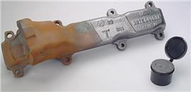
56. The hone is aggressive and will do its work in 20 � 60 seconds. Do not go crazy with it. You can always hone more after inspection, but you can�t un-hone if you go too far. 57. Get a clean rag and run it through each cylinder, rotating it around to get a clean, absorbent surface so that you are not smearing the lubricant around. You want to absorb and clean the interior of each cylinder so that you can inspect them. 58. Now that each cylinder is cleaned out, you can inspect them. Inspection consists of looking down each bore to see that: a. there are no longer any vertical scrapes or gouges b. The color and consistency of the metal surface is consistent in finish and color � no shiny spots. c. There are no cracks or other imperfections in the metal. d. Put your hand in the bore and feel the metal. Your skin will pick up things that your eyes won�t. Your eyes may see discoloration that your skin says is nothing but staining of the metal. Metal surface should look and feel consistent. e. Use your fingernails as a claw, and run them up the sides of the cylinder. They will catch on an edge just a few mm below the top of the cylinder. This is called a �ridge�. f. The relative depth of the ridges in your engine block are important to note. If they are particularly deep or edgy as you run your fingers over them, you will know that this is a high milage engine that is worn. When your mechanic wants you to replace your pistons, it is because he wants to eliminate this ridge by boring the cylinder out to the next size larger, which would make your existing pistons too small, and thus require their replacement. 59. Here is where the subjective part of your rebuild comes in. Most of the engines that you�ll see won�t have a very pronounced ridge. If you have honed the cylinders successfully, they�ll be clean and �restored� and ready for use now (even though the rest of the engine is not). If you re-use your existing pistons, the rings will land in the same spot, and the ridge will not break them. With new pistons, you run the risk of the ring hitting this ridge and breaking. 60. The trick on this is to hopefully discover that your pistons are not terribly worn, and that your cylinders are not terribly worn. This is very subjective. 61. All of the engines that I�ve taken apart which were running and had not been sitting/rusty inside have not needed machine work in the cylinders. 62. Be aware that there is a tool called a Ridge Remover, and it will scrape out the ridge to allow use of new pistons without a rebore. Your machinist deals in absolutes. He must be mechanically CERTAIN that his work is right to the tightest tolerance. His mind is therefore conditioned to make suggestions and choices that are conservative and certain by nature. 63. He will adopt a defensive posture when asked if reassembling the engine as-is seems like a good idea. 64. From his viewpoint, it is not a good idea, since �better� results can be attained by re-machining the engine and installing new parts. He is correct in this regard and should not be argued with or taken to be trying to intentionally gouge you out of your money. 65. The intent of this paper is to suggest that life is a little bit more subjective than the absolute truth which lives in your machinist�s mind. If your collector car will struggle to drive 30,000-50,000 miles in the next 10-20 years, perhaps a workaround solution might be OK? One where the rings are sealing well, the re-used pistons aren�t quite as pristine and tightly fitted, and the ring ridge is still present at time of restart. 66. Here�s the strategy: Reuse old pistons with new rings in honed cylinders. This presumes that the engine will pass inspection, and that you have gone out of your way to explain that you understand the difference between the absolute truth of the machinist�s world, and the shade-tree truth of your own. Once the machinist recognizes that you know the difference between absolute and relative truth, and that you�re willing to accept responsibility for your fate and future, he�ll relax and come over to your side (provided your engine is physically passable and he�s an honest business man). 67. What he wants to avoid is blame for your decisions. If you are not convincing in your conviction that you are in charge and know what�s up, he will not want to proceed. If he�s convinced that you�re there to order his services on a line-item basis, and know that there is downside to what you�re doing, he�ll be OK. Just don�t complain when the engine doesn�t run 100,000 miles or some setback pops up. It�s the blame, recriminations, and bad word that he fears, so be sure to make him aware that you�re cool and not some idiot cry-baby.
MACHINE SHOP SERVICES1. Take everything that is an interior or exterior component of the engine, including the nuts and bolts, down to the machine shop. Since it�s heavy and unwieldy, you should do your shop selection and pre-scouting without the parts. Find your shop, ensure that they do the work in-house, inspect the facilities, get to know the people there, and don�t do business with rude people. I favor older places and people, but if you find a young person that seems qualified, that�s good. The industry isn�t the place that young people go now, since modern engines are somewhat disposable and we�re in the decline of the era of the engine-rebuilding machine shop. 2. Careful! If you don�t like them up front, things will only get worse. You MUST go to at least 4 places and ask the same questions � tell them what you want to do, and see what they say. Ask pointedly what makes them qualified. DO NOT ASSUME ANYTHING � nobody will tell you that they�re incompetent or lacking in tooling, so find someone you feel comfortable with. Smaller independent places beat larger ones in my book but it may be different where you live. Clean, but not too clean, older tooling and machines is what I like. This is not new technology that we�re dealing with here, and you want a place where the fixed costs are already paid for. A new machine that�s still being paid off will come out of your pocket, remember. 3. Print out the next page, but not this one and take it in with you, but you�re better off memorizing it or making a hand-written note so that you can appear to know what the hell you�re doing going in so that they don�t mistake you for a sucker. 4. You want the following services: a. Boil the block, crank, hardware, manifolds, and heads to remove dirt/oil in a hot tank. b. Boil the piston/conrods in an �aluminum� tank, since the system used on the engine block will dissolve aluminum. c. Replace the cam bearings � they are aluminum and will be dissolved in the boiling process. Do not offer that you know this. Wait to see if they tell you that boiling the block necessitates cam bearing replacement. If they do not tell you this, and list it as a separate fee, you�re probably in the wrong place. d. Remove/replace the freeze plugs with BRASS plugs. You can do this yourself, but the extra expense should be relatively minor.
5. Measure the crank bearing surfaces. They should be �stock�. If they are not, you will need to know what they measure so that you can get the right bearings for the crank. Decline the option to polish the crank if it is offered unless you are convinced by the shop that it is required. If the crank is smooth to the touch, I bet you don�t need it. I have not spent $150 on that service yet and feel OK about it, although it is the �correctest� thing to do � another absolute sort of thing that you�re skipping to save money while taking your chances on that decision. 6. Measure the cylinders for required ring size. 7. Complete valve job with hardened seats and new springs (that you will supply). Lightly resurface the head�s mating surface if needed. 8. Exhaust manifolds through the blast cabinet and BOTH mating surfaces on each �faced� so that they are flat. Should come back with obviously ground/flattened mating surfaces 9. If you do not pry the old rings off with a screwdriver, expect this to be a fee. Pull them off yourself before taking them in is my advice. They will not be reused, so breaking them is OK. 10. Get a quote for all of this work. 11. Heads might be $300 each plus or minus $100. 12. The rest of the stuff might be $400 plus or minus. 13. Be certain to get an estimate in writing and set price expectations firmly up front or be prepared to be surprised when fees are tallied. This is crucial to you not getting burned, surprised, or upset later. 14. Be certain to explain that you are not in a hurry, and are willing to wait if slotting your stuff in between high priority work would help the shop manage its work flow.
NEW PARTS1. You will want to shop for as many parts online as possible. Crank and Con-rod bearings, and rings must be purchased in the size that is actually present in your engine, so require measurement before they are sourced. Do not get gaskets from private parties. You want newer sets that have been stored/transported properly and not banged up on some guy�s garage shelf. 2. Rock Auto does well. I have also had success with the local chain store. 3. Shopping around and double-checking ebay is important. You�ll know why when you start seeing some of the surplus items being blown out on ebay for a fraction of retail. BE CAREFUL and shop smart. 4. This is the list of items that you�ll need: a. Gasket set � full engine b. Water pump c. Oil pump d. Fuel Pump e. Temperature sending unit f. 3 cans of spray hi temp engine paint � in your car�s color. Mopar makes all colors that are correct, so don�t settle for what�s on the shelf locally � it�s obscure but findable. g. Oil pressure sending units (1 or 2, depending on your rig) h. Spark Plugs i. Spark Plug Wires j. Thermostat k. Fan belts l. Starter Motor (optional, but suggested) m. Power Steering Pump (optional, but suggested) n. Power steering hoses (mandatory unless replaced in last 4 years) o. Fuel hose � 6 feet p. Heater hose - 12 feet? Double check/measure old ones � careful on diameter! q. Hose clamps � medium for heater, small for fuel, large for radiator r. Radiator hoses � upper/lower s. Cam bearings � 1 set, stock t. Rings � to dimension measured by machine shop. u. Crank and con-rod bearings � to dimension measured by machine shop. v. Engine assembly lube/grease w. Con-rod bolts and crank bolts will NOT be replaced unless they�re obviously failed. x. Carb sent out to carb shop for rebuild y. Radiator to a radiator shop for cleaning/rodding/recoring z. Cam � I strongly suggest getting a new cam/lifters/pushrods/springs from Comp Cams. Get the whole set, and spend the extra $500 or whatever they charge on them. This is an important component that will change the character of your engine. A good �RV� cam, also referred to by some as a �260� cam will give more torque and yield better overall feel from your engine. This is the single biggest return on any dollar you will ever spend on changes, and they�re easy to insert into this process. Please note that cams and lifters wear together, and should be replaced together. There are two styles of pushrods/lifters. Early and late. The Comp Cam computer does not know this, and buying lifters but not pushrods runs the risk of your old rods being too short and therefore incompatible with your new lifters. Do them all together as a package. I got mine all bundled together at a killer price on ebay � saved 40% off individual retail pricing, so look sharp on that. Comp Cams has an excellent 800 number. Call them and DO NOT rely on sellers to choose the right part numbers! You�ll also want the timing chain set, so get the part number for that. It may be available bundled, but need not be Comp Cam version � there are a lot of them floating around ebay for less � you�ll have to check. A spreadsheet is a fast way to start taking notes and comparing. You may save $300+ on the entire project with aggressive shopping, so it�s worth it. aa. OPTIONAL � new valves for heads. I like to replace them, but they�re sorta optional. Your machinist will say YES, DO IT. You can get away without them, but you�re in there and all that�. ab. Take the valve guide seals (from gasket set), valve springs, valves (if new to be used), & cam bearings to the machinist WITH the engine when you drop it off. If they supply the freeze plugs and install them, that�s OK � check to determine who�s supplying them. Machinist may want to supply cam bearings, and that�s OK too. They should install the cam bearings � you don�t want to fiddle with that.
After all of this is done, you�ll have a clean engine, clean and rebuilt heads, and all other parts will be stripped and denuded of paint, grease, oil, and will be just bare metal. Take them home and empty your box of small hardware onto your workbench next to the bench grinder. Install a MEDIUM or FINE wire wheel and get safety goggles if you don�t already have them. Pass all of the small parts under the wire wheel to clean them of residue. Do the same for the other medium size parts, especially sealing surfaces as found on the oil pan and timing chain cover. Prep all parts to be clean and organized prior to your reassembly process. I normally wire wheel the pistons as well, since the aluminum vat does not get all of the carbon off of them. Careful � they are soft aluminum and the wheel will abrade them far faster, so a lighter touch is in order. Now that your engine is clean and ready to re-assemble, the process is essentially a reverse of the prior order of things, with a few special steps thrown in. I will skim over things that should be obvious and cover the things that are different from disassembly.
Engine Reassembly and Sealing:1. Engine back onto the engine stand, block inverted. Garage door down, no air movement, CLEAN working area. Any dirt that gets into the assembly will be bad. Wash your hands and keep things clean. Be meticulous and think through what you are doing on each step. 2. Go to the workbench and take the 8 pistons with you. Also take the box of misc, hardware. 3. Run all nuts/bolts/hardware through the wire wheel to remove the film residue left over from the solvent bath. All of the hardware that wasn�t rusting away on the exhaust system will look NEW when you�re done, and will be nice to handle, indeed, but the wire wheeling process takes patience � there are a lot of bits to work through. Segregate the cleaned parts away from the wire wheel area as you do your work and keep those parts in a clean container after wiping them down. 4. The aluminum tank at the machine shop will not remove the black carbon coke that�s on the pistons, since the solvent for aluminum is less caustic. Wire wheel the entire piston and then run a rag�s folded edge around each of the piston ring grooves to clean them out. I purchased a stainless steel miniature wire wheel made for Dremel tools. I put that in my electric drill, put the drill in the vise on the bench, and then pull the trigger and engage the �hold� function so that the drill runs on automatic. I�ll then run the piston around the drill, with the spinning wire wheel down in the groove all the way around its circumference. After that�s done, I�ll get some aerosol carb cleaner and spray it on a rag (not into the grooves), and then fold the rag over once and rub each of the grooves down all the way around to clean out dust and particulate matter. 5. Now that the engine, crank, and the other parts are clean, you can reassemble. Lay them out in some sort of order on a flat, clean area where you can pick through and grab things without shuffling them around. Try to be organized before you get going to avoid later frustration. I have a wheeled cart that allows me to lay things out in about the geographic order that they go into the engine. I lay things out in order so that I don�t have to rummage or sort as I build. This would include the pistons, which each have numbers 1-8 stamped onto them at the side where the cap meets the rod. 6. A quick note about K&W Copper Coat: I like it far better than silicone, which is frequently used on gaskets by people. This stuff suits me better because unlike silicone or other stuff, it gets tacky and sticky, but never completely cures. This means that when something comes up and you pull your valve cover off, the sealant is what gives way and is still sorta moist. 7. You don�t wind up with a petrified or heat cracked glue that is permanent � it can be taken apart and the cork gasket isn�t destroyed in the process, which is nice. Even if you don�t reuse the gasket, there is something satisfying about peeling it off all in one piece rather than having to wire wheel or chisel it off in crumbly flakes. At least for the short term, anyway.
CAM1. Engine on stand, bottom up. 2. Grease the polished bearing surfaces of the crank with engine assembly lube. This means all of the lobes and all of the bearing areas. 3. Do the same for the bearings already in the engine. 4. Slide cam into the engine from the front, going slowly and carefully to avoid contact with other surfaces as much as possible. Cam head should be flush with the hole on the front of the engine when you are all done.
CRANK1. The freeze plugs were done at the machine shop. If not, coat them and their attendant holes with K&W COPPER COAT gasket sealant and press them into the block with a hammer and a socket with the flat backside of the socket driving the edge of the freeze plug in flush with the ring that it goes into. I put a short extension into the large socket backwards and strike that, or you can find some other flat circular object to spread the force of the blows evenly so that you don�t ding the edges of the freeze plugs. Regardless, the socket is larger than the plug so that you�re driving the edge and not deforming it from the center. That way it won�t fail later. 2. You decided to replace the bearings, because you�re there anyway, and it�s cheap. After the shop measurement of the crank confirmed the sizes needed (likely stock, unless crank was previously or currently damaged, requiring it to be cut smaller, you ordered new bearings for the whole bottom end. Cam bearings went in at the machine shop and may have been supplied by them. 3. CRANK BEARINGS AND CRANK GO IN FIRST. Open the larger diameter (than the con rod bearings) set of crank bearings on a clean, clear table and divide them into two lots � ones with a hole, and ones without. 4. Note that the 5 journals that the bearings sit in on the block have holes in them for oil to come out of to lubricate the crank. Note that only 5 of the bearings have a hole for the oil to go through. The oil hole must not be covered, so take your holed bearings and snap them into the bearing journal. There is only one way to insert a bearing correctly. There is a little tang on one end that fits into a corresponding recess in the block and cap, so look at the engine block�s bearing journal and install accordingly. 5. Pick up each of the bearing caps and insert the non-holed bearings into the caps. The are keyed and only fit one way. 6. A petite hammer can be used to tap the bearing flush with the ears of the journal or cap. The bearings should be flush, squared in their openings, and firmly in there to the point where they won�t move if poked with a finger. The bearing surface is critical and should only be touched with bare fingers that are clean. Dirt should be kept off of this surface. 7. Repeat this process by loading the bearings into the connecting rods. 8. Open the Engine Assembly Lube and put a glob onto each freshly installed bearing in the engine, smearing the lube onto the entire bearing. The center bearing was shaped differently and was a U shape, right? Smear lube on both the middle area, as well as onto the sides. 9. Put a light glob onto your finger and smear it onto the seal that�s in the engine already. 10. Put globs onto each bearing surface on the crank � this is messy fingerpainting, and all shiny bearing surfaces should have an excess of lubricant applied to them, including the side thrust plate areas on the center-most bearing. 11. Put a light skim-coat onto each of the loose main bearing caps also, and set them on a clean surface where the grease will not pick up any particulate. 12. Put a light skim coat of assembly grease onto each of the polished crank bearing surfaces AND the surface where the seal will ride � THIS IS IMPORTANT � the rubber seal must not be mated dry against an un-lubricated, dry crank, or the seal will stick to the crank and spin with the crank. Seal must remain stationary, so crank must have assembly lube on all smooth surfaces before it is installed. 13. Clean your hands so that they are no longer greasy. 14. PERFORM STEPS 25-27 of REAR MAIN SEAL NOW. 15. Pick up the crank and CAREFULLY set it into the waiting greased bearings. You can�t really have too much assembly lube, so don�t spare the horses on this one. Crank should go in one smooth vertical drop and not land cock-eyed. CAREFUL � don�t scratch the polished bearing surfaces or new bearings, so try to get it as square and aligned before setting it in gently. 16. Pick up each of the five bearing caps, with bearings installed and greased only on the face which will touch the crank. They must still be in order 1-5. Pop them atop each of their own bearing journal. They must not be reversed or installed out of order, since the engine�s tolerances are machined in at the factory, and swapping caps is generally not advice. 17. The center bearing is also a thrust bearing, and has flanges on it. Those flanges should have assembly lube on them as well. 18. Get the large bolts that secure the bearing caps out, and dab a drop of engine oil onto each of the bolt�s threads, wiping it down firmly with first your finger, and once in the grooves of the threads, then with a light pass of a rag. You MUST NOT allow oil to pool on the threads or down in the bottom of the hole in the block that each goes into. There is finite space when the bolt is tightened. If there is more oil in that space than there is space, the downward pressure of the bolt can crack the block as it creates incredible hydraulic pressure by pushing on the non-compressible oil. The oil is a lubricant to allow the threads to slide against each other, and nothing more. �Wet� threads slide better than �dry� threads, so get them moist, but not dripping. 19. Run the bolts down into their respective holes and cinch them tight lightly. 20. Try to rotate the crank. If it does not, STOP � you did something wrong, and the time to correct it is before you torque anything down. 21. Set torque wrench to 50ft lbs. Setting is 85, but we�ll start with 50. 22. Tighten the two center bearing cap bolts to 50lbs and try to rotate the crank. It should spin without too much effort. If it will not, STOP � you did something wrong, and the time to correct it is before you torque others. 23. Repeat this process sequentially on each bearing cap, stopping to check that the crank is still spinning and happy. If you go to town on all five without checking each, you�ll not know which is causing binding or problems and may damage things, so take it slow and inspect your work on each new cap as it is tightened. 24. Repeat process, tightening to the factory spec, which I seem to recall, is 85 foot-pounds. See service manual for all specs no matter what, please. 25. Your crank is now installed and has the lower half of the rear main seal installed.
REAR MAIN SEAL1. There is a small baggie inside of the engine gasket kit that will contain two black semi-circular seals. They are the Rear Main Seal, and this is a source of leaks, so should be done carefully. There are also much older versions made out of soft rope, but the fel-pro gasket sets seem to all come with the crescent shaped rubber ones. They are directional � read the included note about orientation and act accordingly. 2. The gasket set will also include some black silicone. Now is the time to break it out. Follow the directions in the gasket set to orient the seal. It will either go < or > in relation to the engine, and getting it backwards is bad news. 3. Smear the black silicone into the large groove that matches the shape of the half-circle seal in your hand. It should mostly fill the channel, and will overflow when the seal is installed and presses on it. The � circle seal is now sitting in its groove behind the rear most bearing journal. Press it in with your thumbs and try to get it even at both ends. Do not stop or abandon the process until the entire seal is installed! 4. Take the clean �rear oil seal retainer�, a cast aluminum plate that has a corresponding seal groove and two bolt holes through it and repeat the process of installing the other C shaped seal into that, being careful that the plate is facing the right direction and that the seal itself corresponds to the instructions and the other � of the seal for orientation. 5. Insert the seal into the silicone-filled groove that it goes into. Wipe off excess with your finger. Should be tidy and neat, but need not be perfect. 6. Take the silicone and run a bead along the bottom face of the seal retaining plate where it will land against the block. Be certain that the bead starts on the rubber seal and goes out to each corner completely � you don�t want oil getting past this barrier later. 7. Run a bead of silicone in the trough or channel that runs up each side of the plate. I like to fill it completely and trowel it flat so that it�s 100% full. 8. Wipe your hands of silicone and proceed to install it in the engine to seal up the back end of the crank. You should have two rubber C�s hitting each other, with a little silicone between them, plus silicone on each side of the aluminum plate that meets the cast iron walls of the engine. 9. Smear a light dab of engine assembly grease or motor oil onto the threads of the 12-point bolts that secure the seal plate, and install. Torque to proper tightness per the service manual. FOLLOW TORQUE SPECS IN MANUAL. 10. SECRET TRICK: The seal retaining plate is now secure in the engine. There is silicone sealant between its bottom surface and the block. There is silicone sealant filling the channels on either vertical side. Take zip ties that are small enough to fit into the vertical, silicone-filled channel, and stuff them in, leaving the heads sticking out. Ties should be long enough to reach the bottom of the channel. Squeeze your fingers together with one hand, and force the zip tie�s tail all the way to the bottom of the channel while your pinched fingers prevent the silicone from being forced out the top of the channel. It will now be forced out the side and fill any gaps between the seal retaining plate and the wall of the block. 11. Use your silicone and a finger or the silicone tube�s pointed dispenser tip to lay a bead of silicone up the outside of both the inside and outside of the perimeter of the rear seal retainer. You want to seal the aluminum to the wall of the block on each side and essentially spackle it in and get that whole area sealed without too much excess material so that oil will not weep out the back of the engine later. 12. Once things are sealed up, use a razor blade first to cut the zip tie heads off at the point that they�re sticking out of the junction between seal retainer and block. Then use the blade to shave down the surface so that the zip ties are flush and you can now run your finger over the junction and have it be smooth. You will notice that the seal retainer is flanged and becomes part of the flanged skirt of the engine that the oil pan will attach to. The oil pan gasket will go across the junction, so it should be smooth and ready for that in the future. 13. Your crank is now installed and spinning without significant resistance, and the rear main seal is in place.
PISTON INSTALLATION1. Read instructions on ring box and install rings carefully, following instructions about the dot on the ring (or whatever they say) carefully. Rings want to go in a certain order and a certain orientation according to instructions. The material is hardened and brittle, and caution should be exercised when doing this. 2. Since the rings are new and the pistons are clean, I like to take them inside and sit on an easy chair so that I can use my lap and am comfortable and can be patient. This is a repetitive process that cannot be rushed. 3. Install the rings, being careful to follow instructions and not spread them open too much. Too much spread and they will snap like a wishbone. You have been warned. 4. Take your 8 pistons and insert the C shaped bearings into them, carefully getting them fully inserted into the con-rod and cap, with the cap and con rod nuts left loose, but in order of 1-8 so that they go back together in order later. 5. Take a sharpie marker and mark the bottom flat face of the con-rod caps 1-8 according to the numbers on the side of the mating surfaces of each con-rod and its cap. Do the same with the pistons � I mark the skirts, but it doesn�t really matter, so long as you�re keeping track of them so that they can be reassembled in order, mated together in order. - You are probably smarter than I am, but it is possible to look at a completed engine and realize that some of the pistons are not in the holes that they were in before despite your best intentions. This is a used engine and everything has worn together, so should be reassembled back the way that it was. This would be less important if all 8 bores were new and everything else were redone, but we�ve taken shortcuts, and reassembly in the original configuration takes on added importance for this reason. 6. Rotate engine so that your first bank of cylinders is horizontal/parallel to the ground. This will make piston installation easier, and I like it better than having the engine right side up, but that is really a matter of style. 7. Get a small oil can with a pump mechanism and liberally drop plenty of oil into each of the rings of your first piston. Grab the rings and rock them left and right in their grooves to get the oil worked in completely. This will facilitate compressing the rings, and avoid unwanted binding when you install the piston into the block. 8. Do the same to the wrist pin that the piston pivots on. The solvent tank will have stripped all lubricant out from between the pin and the piston, leaving it tight or totally frozen. You must get this loose and lubricated so that the piston will pivot relatively freely on the con-rod. This is an important step in the process and must not be overlooked. Too tight and it will force the piston skirts to slap against the cylinder walls and do serious damage. 9. Get your piston ring compressor, and wrap it around the piston, compressing the rings. 10. Use a rag with some clean solvent on it to wipe down the insides of the cylinders. Careful not to get dirt or grit or anything out of the cylinders and into the wet assembly lube that is on the crank where the con rod�s bearing will land! The cylinder should already be clean, so you�re just double checking at this point. 11. Get a can of aerosol lubricant � I like Tri-Flow, and spray it inside the cylinder after any solvent from step 47 has evaporated. 12. Cylinder is now wet with light lubricant. 13. Insert piston into cylinder con-rod first. Once the ring compressor is sitting against the block, get a rubber mallet. Use the mallet to gently whack the piston down into the hole, being careful to hold the ring compressor/piston down so that it does not bounce back up, which could allow the piston rings to pop out in the gap created by the ring compressor bouncing up away from the block. 14. As the piston gets down into its cylinder, the ring compressor will fall away. It will be wet with oil and should be placed on a clean rag consistently between repetition of the steps needed to install each cylinder. 15. With the piston just inside the cylinder, rotate the crank so that the bearing surface for that piston is as far away from the cylinder as possible, and then use the wooden handle of the rubber mallet to gently drive the piston down the cylinder, being careful to get the con rod aligned with the bearing. 16. Slide the piston down to make the con-rod make contact with and then land on the corresponding polished surface of the crank. Insert corresponding bearing cap, and tighten the nuts on the con-rod bolts to 60% of specified torque CAREFULLY, watching for binding or obstructions. If the bearings come loose or something isn�t right, you don�t want to clamp down and force things together, you want to gently correct and then proceed. Do not be a gorilla at this point. Be a watchmaker, ensuring accuracy and fit. 17. Use a wrench and the bolt for the end of the crank to rotate the crank with its single piston attached, checking for binding as you did with the bearing caps. The rings will create additional drag, so note this and allow for that much additional drag as you add each piston. You should be able to immediately spot a bearing that�s too tight and be watching for this. If things were measured and you got the correct bearing sizes, the rest of the assembly of the pistons is the same, with frequent checks at each step to guard against something that�s binding. Taking 7 pistons back out sequentially to locate the one that�s binding is a pain. Do it on the way in! 18. Torque all con rod bolts to full torque. You will have to rotate the crank to do this, and this gives an opportunity for you to miss something, so go sequentially down the block, not just to whatever�s up and open to your wrench at the moment. Failure to torque all bolts to 100% of spec will result in subsequent engine failure, so be SEQUENTIAL and double check the bolts once again before going to next steps.
FRONT END1. Get the cam sprocket, the bolt/washer that holds the cam in place, the cam chain, and the smaller sprocket for the crank out and put them together loosely in your hand. 2. Note that there is a small dot on both of the sprockets. When an imaginary line is drawn between the centers of both sprockets, the dots on each will be on that line and �pointing to each other� or closest to each other. There may be more than one dot on aftermarket sprockets, so read instructions on that. There is only one correct alignment dot for stock, and you don�t want to advance or retard � you want �stock� setting unless you know better. 3. With the timing chain assembly in one hand or laid on a rag, note where the key of the crank must be to allow the two dots to line up. 4. Rotate crank so that it is close to the needed point. 5. Look at where the key slot is on the cam sprocket, and try to rotate the cam to be ready to accept the cam sprocket with the keyway in that position. 6. Install the lower, smaller sprocket onto the crank and gently tap into place so that it�s seated. 7. Rotate the crank, if needed, so that the dot is at 12 when the block is straight up and down � dot should point at the center of the cam. 8. Take the larger cam sprocket and with the chain on it, fit the chain over the smaller sprocket, setting the stage to have both dots aligned on the imaginary line between the center of the cam and crank. 9. Install the larger sprocket onto the crank and double check that the dots line up as you rotate the crank. BE CAREFUL. If you are off by one tooth, it will be impossible to correctly operate your engine. This is a triple-check sort of thing that will get you if you only double check it. 10. Insert, tighten, torque the cam sprocket bolt/washer into the cam. 11. Fit the saucer-shaped oil-slinger over the end of the crank. 12. Get the stamped-steel front cover and insert the circular metal/rubber oil seal ring into it after coating it with Copper Coat gasket seal, driving it in carefully and evently without denting or deforming it. CAREFUL must be driven straight in. A metal plate wider than the ring helps distribute force evenly. Go slow or you�ll damage the part, and they�re challenging to buy separately. 13. Timing chain in, cam in, seal in, get the U shaped paper gasket for the timing cover and apply a layer of Copper Coat sealer to the face of the block that it goes onto, then repeat on the steel cover. The block will have two locating pins in it. Install the gasket onto these pins and then push against the block to get it to hang up and stick to the block so that you can insert the cover without the gasket moving around on you (hopefully). 14. Bottom 4 bolts are larger 9/16� heads, upper are smaller �� bolt heads. 15. Tighten to torque specs after tightening them all evenly to �medium� tightness first. You want the gasket to be evenly mated to, and not have one corner squashed flat before the other bolts are installed. 16. Install the painted harmonic balancer. After painting, you can use white paint to fill the slot that you�ll find in the edge/rim of the balancer. You�ll need this later, and the white is a nice touch. There are also some lines and numbers stamped into the little shelf that�s welded to the front face of the timing cover. This tab hangs out in space over the harmonic balancer, and I like to fill the little numbers and lines with white paint too, but that�s not truly needed. This is the timing mark system that will later be used to set the timing on the engine.
HEADS & TOP END1. Engine right side up in stand. 2. Wipe any and all oil off the top decks of the block. The metal should be clean and dry before head gaskets are installed. 3. Lay head gasket on top face of the cylinder bores, using the alignment pins to locate it properly. 4. Lift head and set it carefully atop the cylinder bank, using the locating pins to �hang� the head on the engine block. 5. Put light coat of lube on the threads of all head bolts. I put a drop under the head of each bolt so that when it tightens down against the head, there is lube to allow me to get it tighter. Just a little bit is all that�s needed. 6. Drop all bolts into their respective holes and use a speed wrench to get them hand tight. Ensure that you install the heat shields for the spark plugs that are stamped steel and look like a large U with holes in the flat bottom part of the U. They go under the head bolts and are located according to where the exhaust manifold dumps are (some are centered, some are to the rear). The flanges of the U should wrap around the exhaust manifold dump to protect the spark plug wires from the intense radiant heat from the exhaust manifold. THIS IS IMPORTANT and should not be skipped or forgotten. 7. Consult Service Manual regarding torque settings AND the order in which the bolts should be tightened. You want to start in the middle and work your way out, laying the head against the block under pressure in an even manner. 8. Tighten all bolts in this pattern to 50ft pounds and then again to the correct torque setting on a second pass. 9. Repeat with the other side. 10. Drop the new lifters into the bores after coating lifters and the insides of each lifter�s cylindrical hole with assembly lube. 11. Reassemble the rocker-arm assemblies, being careful to get them assembled in the correct order, so that they are offset properly, since they can be assembled in one of two configurations. The pushrods should be straight and not canted � let the rocker arms be canted and staggered in arrangement instead of the rods. 12. Use your finger to put assembly lube into the tops of the lifters and the ball-shaped indentations on the rocker arms, as well as on the tops of the valve stems and the rocker arm tips that lay against the valves. 13. Install new pushrods into their respective lifters. 14. Lift the entire rocker arm assembly, with bolts preloaded through their holes, and set it atop the head. 15. With the rocker arm assembly set loosely atop the head, use your fingers to mate the top point of each pushrod into the stamped ball socket that it goes to. 16. Drop some oil into the rocker arms down at the point where they pivot around the shaft, so that when they start rocking, they�ll have lubricant in there and it isn�t dry bare metal to dry bare metal. This can be addressed with assembly lube before you assemble them if you prefer. 17. With everything lined up and laid in place, carefully and un-jarringly tighten the center bolt and snug it down a little, without necessarily tightening the bolt so much that it deforms the assembly. Tighten the middle two bolts finger tight too, then move to the outside. Come back to the center and sequentially tighten them down. When you are done, you�ll have gently and evenly tightened down all 5 bolts and all pushrods will be in place � they tend to want to pop out while things are loose, so keep your eyes open or you�ll have to restart the process. 18. Install the valley pan gasket with the two metal strips with holes in them and six bolts. I put a thin smear of silicone down on the heads and perimeter of the top end to seal things, then another light bead of silicone onto the intake manifold (which needs to be painted before it�s installed in order to get the bottom painted). 19. With valley pan gasket in place, set the intake manifold on the top of the engine between the heads and torque it down. 20. Install the oil-pressure sensor(s) at the top rear of the block � Use new ones- they go bad and leak after a time. DO NOT INSTALL if you plan to use a power drill to pressurize the oil system to test it � see PREPARING THE ENGINE FOR RUNNING, #2, below for that optional step. 21. Install the (painted) water pump manifold onto the block using the supplied gaskets and Copper Coat. 22. Install the new water pump onto the water manifold using gasket and copper coat. 23. Install the water temperature sending unit. 24. Install new thermostat and the old neck using gasket and Copper Coat. 25. Rotate engine so that it is inverted. 26. Thread in the oil pickup tube and land it so that it�s pickup is parallel with the skirt. 27. You may wish to place a magnet inside the pan to collect metal particulate? 28. Coat skirt and oil pan with Copper Coat and install the pan, tightening the bolts evenly so as not to squish only one part of the gasket. 29. Rotate engine to upright position. 30. Using a pair of long-handled needle-nose pliers, insert the distributor drive gear in through the distributor hole. Please see Service Manual about this. The flat slot that you see in the top must be horizontal when the engine is at Top Dead Center, as this drives the distributor. There is a whole set of things that must be lined up � gear in correct position, crank in correct position, distributor rotor in correct position (possible to have blade on end of distributor be correct or 180 degrees out � you must read the instructions in the FSM for this � it�s not that hard, but the manual relates this better than I can here. 31. Invert the engine or rotate it sideways. You will want to look up the oil pump hole and see how the distributor drive shaft�s blade is oriented, and then twist the oil pump around as it is inserted in order to get the slot in the oil pump lined up with the blade on the end of the driveshaft. �all without popping the distributor drive gear back out as you push the oil pump in from the bottom. Not as hard as it sounds, just need to get them mated without upsetting the driveshaft as you do so. 32. Lubricate oil pump�s nose and O ring with motor oil. Lubricate oil pump hole in engine with motor oil so that it is �wet� to allow the O ring to slide inside the hole without binding. 33. Coat pump and block with Copper coat, and install gasket onto block. 34. Install pump and tighten down the 4 bolts that hold it in place after �wetting� bolts prior to insertion. 35. Install fuel pump. There is a polished cylindrical rod and a allen head plug needed to do this. Grab the rod and coat it with assembly lube. The lube will be sticky enough to hold the rod in, or if not, the engine can be rotated to use gravity to help you. Insert through threaded hole at bottom (if looked at when engine is right-side up). Actuating rod must be in BEFORE you insert the fuel pump, which then gets tightened down with its� two bolts. The plug gets some Copper Coat on the threads and is then tightened into the actuating rod�s threaded insertion hole to seal it. 36. Check valve covers to see if the holes that the bolts go through were deformed by over-tightening. Re-flatten with a small hammer on an anvil or flat surface before reinstalling � the cover metal should be flat where it mates to the gasket! 37. Rotate engine to upright position and install the valve covers with the bolts only finger tight and without sealant � they�re coming off later. 38. Plug the hole that the distributor goes into with a wad of paper or something to keep paint out of the interior. 39. Paint the entire engine the color of your choice, using engine specific paint. You sourced this in advance, and the paint is where it all comes together. 40. Nobody ever got in trouble for using too much paint. I like to do 4 coats, but you may want to do otherwise. Just be sure to wipe down any grease or finger prints before you start your work, Picasso.
Prepping the engine for running1. Remove paper wadding out of the distributor hole. 2. Not required: If you want to test the oil feed system, you can remove the distributor drive shaft and look down the hole to see the oil pump. It has a hex shaped hole. There are long hex-shaped rods available to insert in your drill, or you can use a long extension with a hex key attachment on the end. If you decide that you want to test the oiling system, you can use a power drill to drive that hex head as if it were a spinning distributor. (Fill the engine with oil first). Remove the valve covers and run the tool. You can then see if oil is flowing through the rocker arm shafts and coming out and running down the heads and back into the engine. I had an engine that didn�t do this on one side once. It made a lot of racket at startup on one side. I pulled the valve cover and found it dry (except for the assembly lube). I do this test because I have the tool, but it�s a step you can skip, so I left the tool off the to-do list. Depends on how conservative you are. If you do this test, it�s also a good idea to refrain from installing one of the oil pressure sensors and going until oil just starts to come out there, as well � you don�t want to pump globs of oil out the hole and get it all over. There are also pressure gauges that can be bought to screw into the oil hole at the rear. That�s more money, and I figure that if I see oil, then there�s going to be pressure and the passageway is clear. Your call. 3. Install the valve covers by coating first the ring around the head and then the cover itself, then soaking both sides of the cork gasket so that the gasket absorbs the sealant, placing the gasket onto the wet surface of the head and then putting the cover on next. 4. Get all six bolts started, then tighten the lower ones first. Tightening the upper two last will �rotate� the cover down, and put additional tension against the lower edge, hopefully improving the seal there, where it is most likely to leak. 5. NOTE: Your car probably has male bolts. They make threaded shaft/studs with nuts. The threaded studs screw into the head and then stick out, waiting for the valve cover and gasket to go on them, and they are available as kits. I like this method better, since it allows me to �hang� the gasket on the head and keep it aligned as I lower the cover into place. The gasket can squirm around otherwise and fail to seal, even with the little tabs that are supposed to hold it in place on the valve cover. I bought ones on ebay marked �Chevy� � they�re all the same thread pitch from this era, so small block chevy (SBC) ones should be fine. 6. Your two exhaust manifolds should have been bead blasted clean and the faces that mate to the engine and exhaust filed flat, or �faced�. They should be shiny and flat with horizontal scuff marks from the tool. If not, get them faced before installing � this is important, since they deform over time through heat cycling. This will ensure that they mate and seal well to the engine and exhaust with no leaks. 7. The manifolds are mounted onto the head with studs that screw into the head. They ought to already be in the head when you get it back. If not, note that they thread through holes and stick into the water gallery on the other side, and if not sealed, will weep water. Put hi temp silicone on the threads before installing if you have to. Use a wire wheel to dress the mating surface of the head before you install the supplied gasket. Put the metal face (if there is one) on the head facing the head, so that upon removal you don�t leave a bunch of gasket material on there, since it�s easier to clean the removed manifold than it is to clean the head. There should not be paint or other material on there � just a nice, flat surface for sealing. Since this is air and not liquid, it�s a little more tolerant of irregularities, but it�s nice to be sure. 8. Smear the CALYX Manifold Dressing onto the bare metal of the manifolds. Coat every part of the manifold with this dressing, but do not do the mating surfaces. The manifolds get incredibly hot with use, are cast iron, and as they cool, they attract moisture from the air and rust. Fast. The rust will make your new engine look old fast, and this dressing makes them look like the metal is fresh and bare. It can also be re-applied over time if you care. Re-apply only when the engine is cold. This is a cheap and easy way to make your engine compartment look really nice. 9. Install the exhaust manifolds, using proper torque. 10. Install any other remaining loose items, such as the motor mounts, painted front pulley, etc. 11. Install correctly gapped spark plugs. 12. Do an inventory and check that nothing is left to be installed besides the distributor, carburetor, and wiring harness. 13. See the service manual about how to set the distributor drive shaft correctly when the engine is at Top Dead Center (TDC). 14. Set engine to TDC and get the slotted driveshaft in with the slot horizontal, and install the distributor. 15. Distributor has a rotor, and rotor can face either one way or the other if spun with your fingers as you install it. Since engine is at TDC, rotor should point to the #1 spark plug wire on the distributor. There are detailed drawings/descriptions of this in the Service Manual. 16. Install cap & wires with special attention paid to wire routing to keep wires off/away from exhaust manifolds that will melt them. Start from the back and use the longest wire to go to the #8 plug that�s farthest away from the distributor and so forth. You may wish to get some small clips from the parts store to hold the wires together as they wind across the engine. Looks neater and keeps them off the manifolds. 17. Stuff paper down the intake manifold holes. Carb goes on after engine is in the car so that it does not get damaged in the process of installation. 18. Reinstall the AC compressor now or once the engine is in the car. I like now so that I don�t have to heft the compressor over the fender and fiddle with it when stretched out. 19. Put the sling chains onto the engine and lift engine into the car � with or without transmission, depending on how you decided to do that. 20. Bolt engine or engine/trans back into the car. 21. Reinstall radiator that you (hopefully) had flushed, rodded, or recored. If you don�t do the radiator at this time, the funk inside of it will go into your nice, clean engine. It may also be plugged up and possibly cause damage to your engine later � DO THIS NOW! It�s only money, and you only have a chance to do it right once. 22. Install radiator fan shroud, if car has one. Most do. Why doesn�t yours? Wasn�t it supposed to be there? Make sure you�ve got one if you didn�t before. 23. Re-attach spinning accessories: a. Starter b. Alternator c. Power steering pump d. Fan & pulley e. Fan Belts 24. Install carburetor and linkages. See service manual if you did not mark where the kickdown linkage was attached. It�s adjustable. You can also get that adjusted by the transmission shop that rebuilt your trans if you ask them nicely in advance. It�s simple, but poorly explained in the service manual, and I�m not sure I can do better here, so you�ll want to ask about that when everything else is done and the car is running/driving. 25. Reinstall wiring harness connections 26. Reconnect the exhaust pipes using new bolts and the supplied gaskets. 27. Reconnect fuel pump to chassis and to carburetor using NEW fuel line. 28. Engine should be completely connected now, but I�m not there with you, and I suppose that I�ve forgotten something. Inspect everything. Double check that there is oil in the engine and fluid in the transmission, and that the transmission connections/cooling lines/etc. are all connected. Double triple check everything looking for loose parts, left over hardware, etc. 29. Connect the battery. 30. Prime carb with fuel. 31. Reinstall hood, being certain to get it aligned correctly before shutting it completely. 32. Start car. Have a buddy turn the key while you gently twist the distributor left to right. I find that the vacuum advance thingey normally points to somewehere between 1 and 2 o�clock. See the photos of your BEFORE engine to refresh your memory, and get the thing close before starting the process. 33. Engine �should� start. 34. Use a timing light to set the timing as detailed in the Service Manual. I think that it�s 8 degrees before TDC (from memory), but you should double check specs. 35. At startup, the engine may produce smoke or smells that are new. This is excess sealant or oil burning off for the first time. As long as you don�t see flames or billowing smoke you�re OK. If it seems excessive, stop the car and investigate. You may have failed to seal someplace. 36. The engine may weep water. I have had them weep out of the exhaust manifold bolts. Double check that studs were properly tightened by removing the manifold if needed. You ought to have been careful on these, but I wasn�t once�.. 37. Light weeping of water isn�t totally unexpected. You can get the silver �Radiator Stop Leak� at the auto parts store and run it through the engine to stop incredibly minor leaks found at the freeze plugs or exhaust bolts or water pump, but be careful not to ignore a more serious water leak � those don�t fix themselves. BE PATIENT with this � it�s important. 38. Drive car on short hop around the block and reinspect. I normally take a wrench to loosen/adjust the distributor (there is a special one that you don�t really need, but is nice, called a �distributor wrench). The engine may ping. Adjusting the distributor by rotating it a few degrees, ever so slightly clockwise or counter clockwise will make the engine perform better. 39. Be certain to disconnect the small diameter distributor vacuum line from the engine and suck on it or use a vacuum pump while the distributor cap is off to verify that the vacuum advance mechanism is functioning. If it isn�t, it should be replaced. This will make a big difference in highway performance. 40. Drive car sparingly for first 500 miles, and replace oil/filter then. You may wish to research engine break-in procedures. There are many thoughts on this. I try to bed/wear everything together under light load before pushing the engine hard. Granny it around and be gentle until everything has settled in, and you should be AOK. Keep an eye on things under the hood, and be vigilant of your gauges. If you made a mistake or something is going to fail, it�s in the break in period, and you want to be ready to shut the engine down and inspect/correct before you do damage.
Good luck! YOU CAN DO THIS
|
This page last updated July 1, 2011. Send us your feedback, and come join the Imperial Mailing List - Online Car Club