
Imperial Home Page -> Repair -> Steering -> Terms
From Philippe (Imperial Power Steering Units):
Coaxial power steering was used on the 1957 models (and perhaps before but isn't the same housing) but the 1958 used the Constant Control power steering (except some earlier '58 models which have the Coaxial). The Constant Control was used until '64. The Coaxial has a very long housing which protrudes below the dash. That explains why there's a removable plate on the floor: you couldn't remove the steering assembly without removing the plate! You "extract" the steering from inside the car. The plate remains on the '58 but you could remove the Constant Control steering from under the car. The '58 Constant Control has a round "bell" cover at the top where you find the adjusting screw, the '57 Coaxial has a square cover for the adjustable screw.
Recirculating
Ball and Nut Steering Gear
Rack-and-Pinion Steering Gear
Steering Linkage
Inspection and maintenance of the steering system is important because a steering problem can lead to an accident. The steering system has two critical inspection and maintenance areas: the steering gear and the steering linkage. Two basic types of steering gears are in use. One is the recirculating ball type and the other is the rack-and-pinion type. Both may be operated manually or with the aid of hydraulic power. The next sections describe the parts and operation of the manually operated steering gears.
The larger and heavier the car, the more difficult it is to steer. Most large American cars are equipped with a recirculating ball-type
steering gear. This type of steering gear is very low in friction and provides a good mechanical advantage for a heavy vehicle.
The recirculating ball and nut steering gear consists of several parts contained in a steering gear housing. The steering gear shaft is connected to the steering wheel either directly or through some type of flexible joint. There is a worm gear on the end of the steering gear shaft. A cross (Pitman) shaft is mounted in the housing in a position 90 degrees to the worm gear. A ball nut rides on the worm gear and a gear on the cross (Pitman) shaft, called the cross shaft sector, is engaged with this nut.
Ball or roller bearings are used to support both ends of the worm gear and are adjustable to remove end or side play from the worm gear. The cross (Pitman) shaft is supported by bushings, needle bearings, or a combination of the two, and provision is made to control the worm and cross shaft clearance. All parts are enclosed in a cast housing that is partly filled with lubricant. Seals are used to prevent the entry of dirt or the loss of lubricant. Provision is made to bolt the steering gear housing to a rigid area, usually the frame.
The ball nut has internal threads that
are meshed to the threads of the worm with continuous rows of ball bearings
between the two. The ball bearings are recirculated through two outside loops,
called ball guides.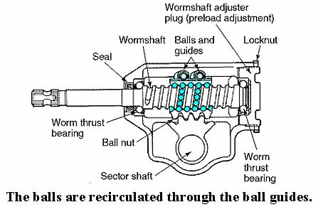
The sliding ball nut has tapered teeth cut on one face that mate with teeth on the sector. As the steering wheel is rotated, the nut is moved up or down on the worm. Because teeth on the nut are meshed with the teeth on the sector, the movement of the nut causes the sector shaft to rotate and swing the steering linkage connected to it.
The recirculating ball construction results in a friction-free contact between the nut and the worm. When the steering wheel is turned to the left, the ball bearings roll between the worm and the nut and work their way upward in the worm groove. When the ball bearings reach the top of the nut, they enter two ball guides and are directed downward into the worm groove at a lower point. When the steering wheel is turned to the right, the ball bearings circulate in the opposite direction.
The recirculating ball steering gear has the disadvantage that it occupies a good deal of
 space, usually in the engine compartment. The rack-and-pinion steering gear
was first developed for compact cars in which the engine compartment space was
limited. The rack-and-pinion system has worked so well that it is currently
being used in both imported and American compacts and intermediate size cars.
space, usually in the engine compartment. The rack-and-pinion steering gear
was first developed for compact cars in which the engine compartment space was
limited. The rack-and-pinion system has worked so well that it is currently
being used in both imported and American compacts and intermediate size cars.
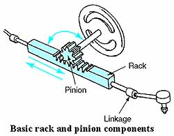
The basic parts of a rack-and-pinion steering gear are shown below.
The steering wheel and steering shaft are connected to a pinion gear. The pinion gear is in mesh with a straight bar that has gear teeth cut into one side. The toothed bar is called a rack. When the driver turns the steering wheel, the pinion gear turns, causing the rack to move. This movement, in turn, is connected to a linkage that moves the front wheels. The
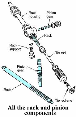
rack-and-pinion gear is mounted in a rack housing assembly. The steering linkage
consists of two inner tie rods and two tie rod ends. The inner tie rod ends are
attached to the steering rack ends. The outer tie rod ends are attached to the
suspension arms on the steering knuckles. Rubber boots are used to cover and
protect the inner tie rod assemblies from road splash.
The
rack-and-pinion gear is mounted in a rack housing assembly. The steering linkage
consists of two inner tie rods and two tie rod ends. The inner tie rod ends are
attached to the steering rack ends. The outer tie rod ends are attached to the
suspension arms on the steering knuckles. Rubber boots are used to cover and
protect the inner tie rod assemblies from road splash.
With a rack-and-pinion steering gear, the rack is connected by linkage directly to the steering knuckle. Recirculating ball-type steering gears require a more complicated linkage to change the rotary output of the sector shaft to the back-and-forth movement of the wheels. A steering linkage consists basically of a steering gear Pitman arm, a center-link, and a tie rod assembly connected to each
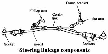 other by ball sockets. The Pitman arm is splined on the steering gear
sector shaft. When the sector shaft turns, the Pitman arm swings in an arc.
The swinging end of this arm is connected to the center link.
other by ball sockets. The Pitman arm is splined on the steering gear
sector shaft. When the sector shaft turns, the Pitman arm swings in an arc.
The swinging end of this arm is connected to the center link.
The center link (also called drag link or relay rod) transfers the swinging motion of the gear arm to a linear or back-and-forth motion. It can also change the direction of the sector shaft arm motion, depending on the type of linkage. The center link is connected to the tie rods. These transmit movement of the relay rod to the steering arms. The steering arms are part of, or attached to, the steering knuckle spindle assemblies. When the steering arm moves, the steering knuckle assembly rotates on the suspension control arm ball joints.
Tie rod ends are used to connect the tie rods to the center link and to the steering arms. They are also used on the end of the sector shaft arm and the idler arm. Adjustment of the tie rod length is provided in threaded sleeves that are locked by clamps.
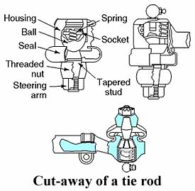 A
tie rod end is a ball located in a socket. The ball is attached to a tapered
stud. A spring or plastic spacer holds the ball in position in the socket. The
tapered stud fits into a taper in a steering arm and is held in position by a
threaded nut. The ball and socket allows up-and-down movement between the tie
rod and the steering arm as the car goes over bumps. The ball and socket also
allows back-and-forth movement as the driver turns the steering wheel. Grease is
held between the ball and socket with a grease seal.
A
tie rod end is a ball located in a socket. The ball is attached to a tapered
stud. A spring or plastic spacer holds the ball in position in the socket. The
tapered stud fits into a taper in a steering arm and is held in position by a
threaded nut. The ball and socket allows up-and-down movement between the tie
rod and the steering arm as the car goes over bumps. The ball and socket also
allows back-and-forth movement as the driver turns the steering wheel. Grease is
held between the ball and socket with a grease seal.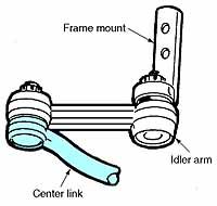
In most steering linkage arrangements, one end of the center link is supported in the Pitman arm. The other end is supported by a frame-mounted idler arm. The idler arm pivots in a support attached to the frame when the steering linkage moves back and forth.
WARNING: All steering linkage parts are
manufactured from malleable materials and will bend, distort, or deflect rather
than fracture under extreme shock loads. This toughness and malleability are
necessary to avoid the complete loss of control that would occur if any part of
a steering linkage were to break. Steering linkage parts must never be heated
during a repair because this could cause them to lose their malleability and, as
a result, fracture.
This page last updated April 8, 2003. Send us your feedback, and come join the Imperial Mailing List - Online Car Club
