Imperial Home Page -> Imperials by Year -> 1967 -> Turn Signal Replacement
|
It all started while on the way home from the local Imperial Club Christmas party. I was driving my 67 Crown, my brother-in-law was behind me in his 68 Crown. Suddenly my cell phone rings and its my brother-in-law. He tells me that my brake lights are not working. We pull into the next gas station and I do a quick check under the dash but find nothing obvious. So I decide to take my chances and hit the freeway for the 100 mile drive home.
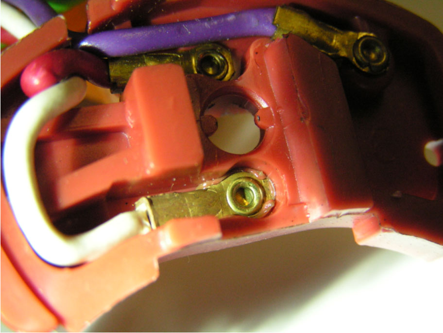
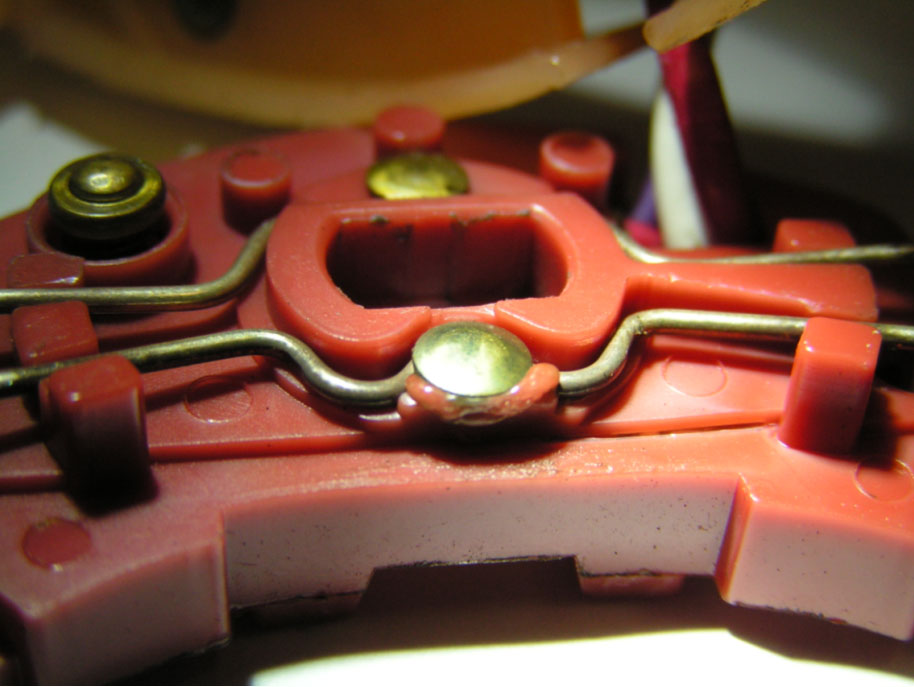
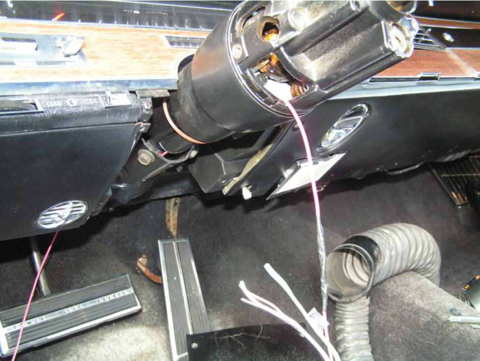
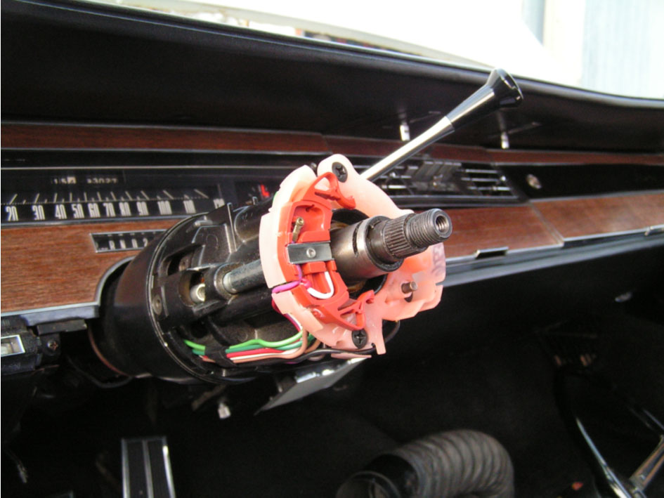
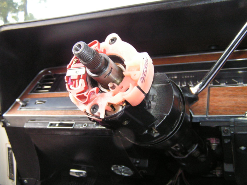
The following weekend was my next opportunity to investigate the problem. I traced the voltage path from the fuse block through the brake light switch up to the turn signal switch. After that it disappeared. The next step was to pull the steering wheel. Getting the wheel and the assorted horn assembly removed was pretty simple and easy. Removing the Tilt Actuator Cover was another story. I modified a slide-hammer bearing puller to do the job. A few hefty slams against the slide stop and the cover finally popped loose. Turn signal switch was now fully exposed and my troubleshooting could continue. Voltage was still present on the incoming white wire but not on the dark green wire for the left rear signal or the brown wire for the right rear signal. Very close inspection showed where some of the plastic material in the switch had become warm enough to start melting. It melted enough to form an insulator between the wire terminal and the rivet going through to the other side.
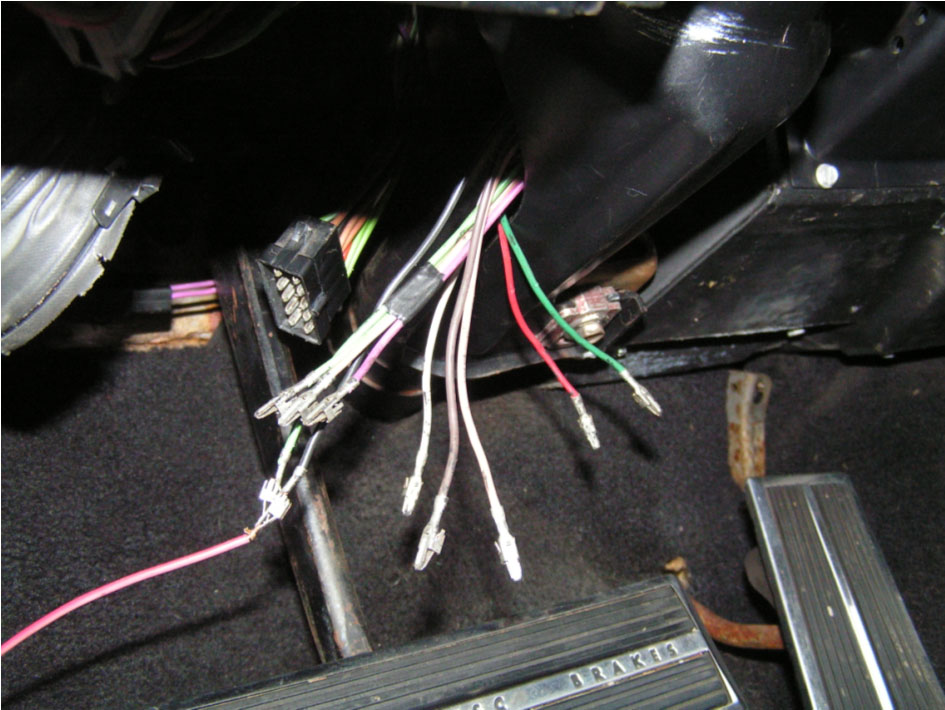
The white wire carries all the current for the six brake lights when you step on the brake petal. Removing the signal switch was not too difficult. But I did find it easier to cut the terminals off the end before pulling it through the steering column.
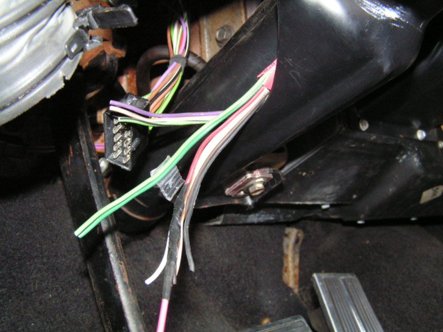
Make sure you attach a pull-wire to the bundle before you pull it out. This will make pulling in the wire for the new switch much easier. You will have to pull the new wire into the steering column with the connectors on the ends. It will be a bit more of a challenge but with a little patience it can be done.
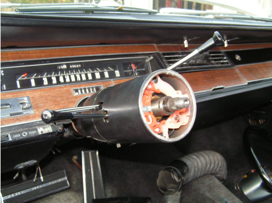
New wire ends ready to be pushed into the connector body A couple of shots after the new switch is successfully installed.
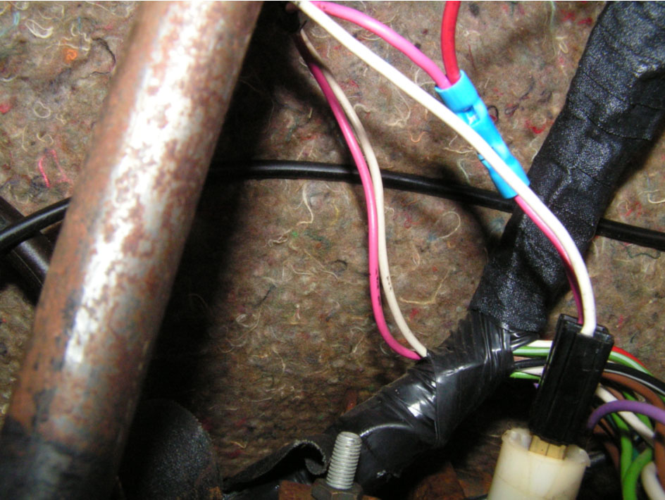
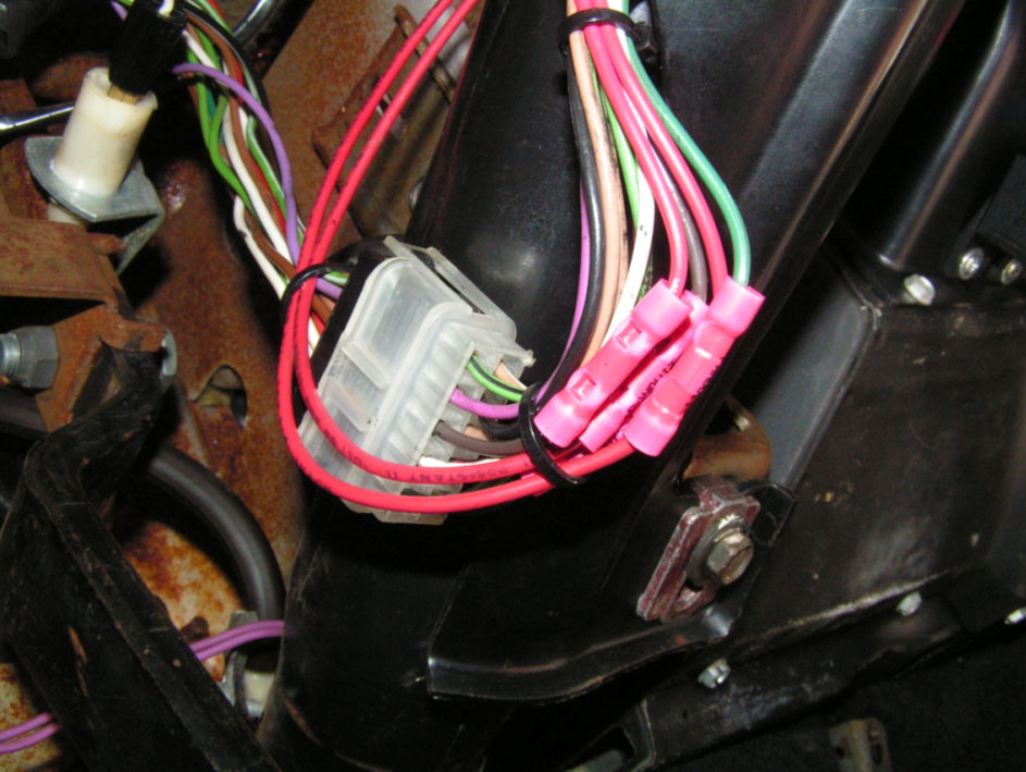
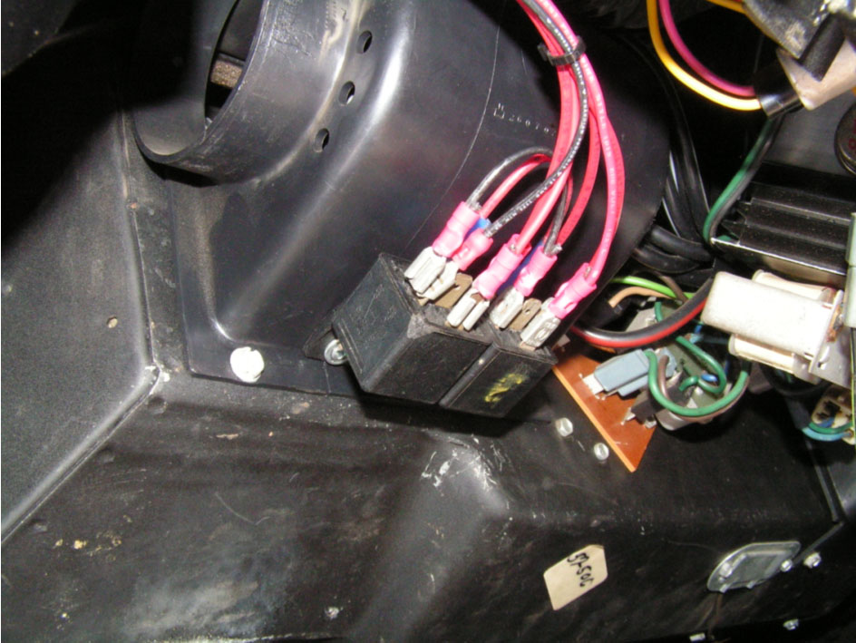
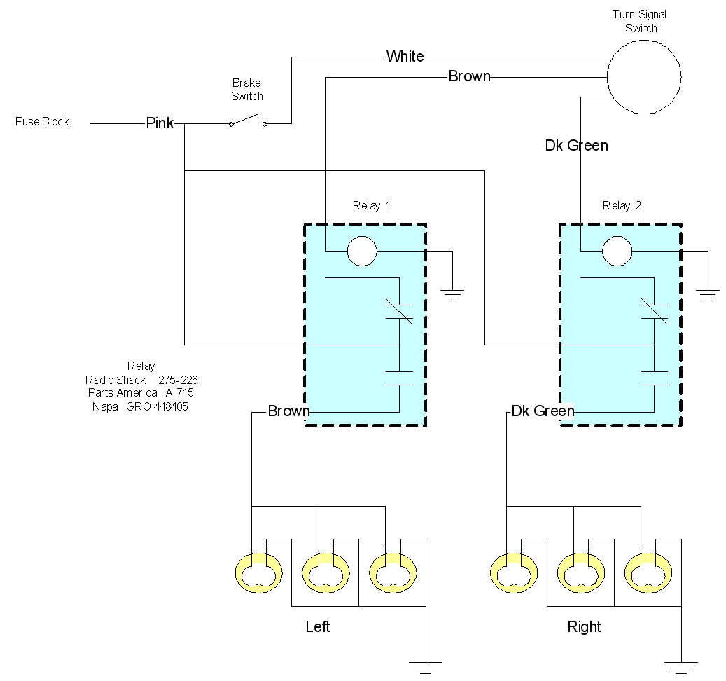
After going through all this I figured it would just be a matter of time before I had to do it all over again. If you live in an area where you have to deal with stop-n-go traffic and spend a lot of time with your foot on the brake this will happen again. So I decided to eliminate the load from the turn signal switch. I did this by routing the brake light current around the turn signal switch. The only load going through the turn signal switch is the relay coils. These are a few shots of the installed relays. The feed voltage is taken from the pink wire between the fuse block and the brake light switch. The dark green (right rear) and brown (left rear) are used to trigger each of the relays. This is where I tapped into the pink wire going into the brake light switch. This was the easiest place to interrupt the wires going to the rear lights. I attached the two relays (with very short screws) to the plenum. These relays are readily available at Radio Shack or Napa Auto Parts. (I had these in the garage) Make sure you replace your regular turn signal flasher with an electronic model. The regular flasher will not work because the load for the lights is not running through it anymore. Another advantage to this setup is that now I can hear the turn signals.
|
This page was last updated 24 February 2007. Send us your feedback, and come join the Imperial Mailing List - Online Car Club