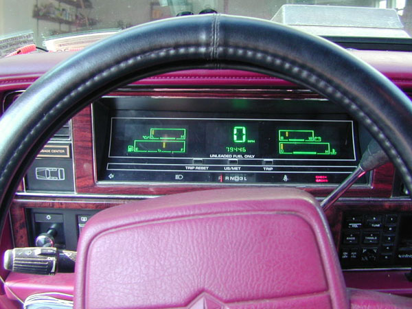
 Here is a 1992/1993 Digital Dash I have spoken to many AC/AY owners over the last few years. Most who have gotten rid of their car, or left it in a yard while in need of repair, chose to neglect their car because it just didn't have enough options for them to justify the repair costs. I've also talked to many AC/AY owners who have wished that their car was just a tad more loaded. I forget if it was Brad (a '90 Imperial owner), or another Imperial owner, but someone with a 90's Imperial mentioned tome that they have the analog dash and would like the digital cluster(as that's more "Imperial"-like, remember.... all 80s Imperials got a full LED digital cluster.....). In order to do this very complex swap, you need to know how the system works. Basically you have a large electrical system in these highly computerized cars. The PCM controls spark, fuel, the TCM controls the tranny- and a 3rd major computer, the body computer, controls the options, alert sensors, etc. ALL OF THE INFORMATION BELOW IS FOR c1990-1993 AC/AYs. THIS HASNOT BEEN CHECKED TO SEE IF IT WILL WORK ON PRE-1990 AC/AY's. AS ARESULT, THIS INFORMATION MAYBE VERY DIFFERENT FOR EARLIER MODELYEARS. THIS INFORMATION IS ALSO STUFF I FIGURED OUT USING A 1990 FSMAND MY BRAIN- AND SO ALL OF THIS INFORMATION IS PRESENTED AS-IS ANDIS FOR EDUCATIONAL USE ONLY. IF YOU DO THIS AND ANYTHING BAD HAPPENS,IT AIN'T MY FAULT. ALWAYS USE A FSM FOR YOUR MODEL YEAR WHEN DOINGTHIS KIND OF WORK, KNOW WHAT YOU ARE DOING, AND SEEK PROFESSIONAL AIDIF YOU ARE EVEN A LITTLE UNSURE OF RATHER OR NOT YOU CAN DO THISRIGHT ON YOUR CAR. I have also left out color codes, how stuff wires together as that changes a little from year to year and I don't want to confuse anyone by mentioning what the 1990 FSM listed vs. the actual wires in my 1992 3.3 Dynasty.... All this information is included with the story of how I did this on my Dynasty (1992 3.3) below, along with some of my ideas for improving the system. The body computer controls several different circuits. On analog AC/AY's, you had the idiot lights in the cluster. The body computer ran a circuit for each idiot light. Then you had the actual gauges in the cluster. The volt meter is an actual volt meter which reads the positive DC voltage going to the cluster. The other gauges get their inputs electronically from sensors, circuits throughout the car. When airbags entered FWD Mopars, the body computer came to control those too, and a CCD Bus was created. This buss (uses two wires)carries computer code from the body computer to the diagnostic port. When the Mopar diagnostic tool is plugged into the port (on my Dynasty, this is the blue 6-prong port by the release e-brake handle) the tool translates computer code made by the body computer into useable info. The body computer makes up the code in such away that the code contains all kinds of information about the car which is sent out through the CCD Bus in real time. And so with the diagnostic tool, you can see how fast the car is going and compare it to the speedo to see if your speedo is working, etc. Note that this data bus is CRITICAL for your computers to operate(that means BCM, PCM and TCM). The digital dash uses idiot lights in almost an identical manner. The gauges on the digital cluster are not gauges at all (other than the voltmeter) but rather are LED displays. The cluster takes the CCD Bus and translates it in real time and tells the LED displays to "display" the information to you as it is written by the Body Computer. Because of this, the wires used by the analog cluster(which carry real-time sent electric signals from the sensor circuits themselves- not the body computer) are not all used by the digital dash. The trip meter on the digital cluster is controlled by a separate "trip controller" located elsewhere in the car. This unit is not part of the cluster or the body computer themselves... The CCD Buss its self changed almost every year. Every time any idiot light circuit, airbag code, introduction of an other circuit occurred, the body computer changed a little- and with each change, the digital cluster was changed so it could de-code the CCD Buss- and so a 1991 cluster will only work in a 1991, '92/'93 in a '92/'93,etc. The first thing you want to do is get your hands on the FSM for your model year and copy every page for the AC/AY in the electrical circuits volume. For my 1990, this is about 180 or so pages... this step is un-needed if you own your own FSM (they go for about $25 per volume on eBay...). Then you take a piece of paper- and draw three things on three different pages- 1) How your currant analog cluster is wired up(showing wire colors, pin #'s and pin locations, etc). Mention what each wire is for (i.e. black wire goes to pin A, and is black). 2) Do the same, only for the digital cluster. 3) Now compare the two. Some wires are identical and are "shared"- i.e. the analog ground is the same wire as for the digital ground, etc, etc. You'd find that out of the 13 pins used by the digital cluster, about 8/9 of them can be obtained via the old analog wiring. Now disconnect your battery and remove the trim covering the front of the dash on the driver's side. Basically the top bezel unscrews from the lower bezel unscrews. Then unscrew the plastic panel which goes under the steering column and has the e-brake release handle. Remove this piece and set it and the trim pieces aside somewhere safe. Now slowly and carefully remove your analog cluster- it has two connectors/harnesses (one on each side) so be careful! With the analog cluster out, cut off the existing electrical connectors/terminals for the analog cluster- and leave about 2" of the ends of the wire attached to these connectors. This way, if you want to go back to analog later, you already have the connectors with the right colored wires already attached. Now you have a choice- you can do what I did (not recommended) and take your digital dash apart and unsolder the male pins on the back of the cluster from the PCB and then solder wires directly to the PCB. Then you can run these wires out the back of the cluster and splice them to the wires you need them to go to. Or, for a more plug-and-play approach, obtain the female connector harness which plugs into the back of the cluster. Don't know what they go for at the dealer, but you could grab one from a yard....then solder the wires to the connector and just plug it into the back of the cluster. ALL electrical connections you make MUST be soldered. That way, there is less of a chance the dash will suddenly stop working when you need it to work (i.e. at night and your radar detector goes off-or you get into a speed zone change and the speedo-quits and you have no idea how fast you are going.......). With the electrical connections made, triple check the connections to not only ensure the connections are good electronically, but to ensure that the correct wires go to the correct places. I suspect you could kill your cluster if it is wired up wrong. Now- with the cluster not yet put back in the dash, reconnect the battery and put the ignition switch in the on position- don't start the engine yet! The cluster should light up, show how much fuel is in the tank, show the amount of miles on the engine, show the correct amount of volts in your electrical system. Everything should light up equally bright during the start-check. Turn on the headlights- the cluster should dim significantly. Turn off the headlights. Check the blinkers, one at a time, etc, etc to check and see if the blinker lights on the cluster work, etc. Now start the car- the fuel level, temp, oil pressure, everything should be in perfect operation. However when I did all this, everything was operational- and perfect- and I was ready to put the cluster back in- but I heard aloud buzzer. Apparently there is some short of glitch with hooking up the cluster in this manner which I have yet to identify. For whatever not-yet known reason, with the digital cluster in, the alert buzzer(sounds an audio alert when something is wrong- i.e. when the keys are left in, lights left on, door left open, the audio alert is sounded....) gets stuck on. Stuck on ALL the time (as in the buzzer is on all the time including when the car is off). This glitch will drain the battery if not corrected. I started pulling fuses- and apparently fuse #8, when pulled, stops the buzzer. Bad part is that with fuse #8 out, the dash, idiot lights, message center all turn off as well! So I tried re-wiring the dash so that the cluster uses a different fuse. After that I got the cluster and most of the idiot lights back. My airbag light is also always on- I suspect that this issue is body computer related.... with this setup I have digital dash minus the alert buzzer, message center, and trip computer. With the installation complete, I have tested the car at day and night driving and have concluded that the cluster is no where near bright enough during use when the headlights are on. I plan on going back into the cluster and modifying the PCB so that either night use includes the use of all the pilot lamps in the cluster or has more pilot lamps (which only come on at night). I never use the trip-meter anyway, or the message center, so that's all fine with me. If I wanted the message center operational, I would have a switch so that when a switch is pressed, a wire with an in-line fuse shorts out where fuse #8 goes- thus allowing the message center to work (while still having a fuse). The buzzer would also be on at that point, but turning the switch off would end the buzzer and the message center. I also plan to go back in and again try to locate that buzzer so I can remove it. I can't locate the buzzer to date, so I may try clipping the wire going to pin #4 on each of the two large body computer harnesses (one of these pin#4's is for the key-in chime circuit, the other is for other circuits which use the buzzer...). The modification looks and acts good for me (besides the message center and buzzer issue). Hopefully I can and will determine the correct way to resolve the remaining two issues soon. The entire project took me a really long time. I took a whole weekend off- started work on a Friday night at around 6PM, kept working until 7 AM when I took 4 hours of sleep, then kept working until I was done on Sunday at around 10 PM. So Needless to say, it takes a while. I wouldn't advise this mod to anyone who isn't familiar with electronics and doesn't mind messing around with the car.s electrical system:) Update! It ends up that the message centre and headlight switch are both wired differently on digital dash cars- so my analog wiring of the two were causing the conflict that was causing the alert. Go through the FSM and make sure your other circuits do not get wired differently for digital dash models. 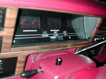 The Digital Dash installed in my Dynasty
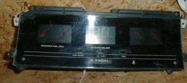
Update #2! A couple years after I did this mod, my digital dash cluster died! Sadly no local yard had an other one, so I had to switch back to the analog cluster. A year later, early 2006, I was able to find a 1988 Chrysler New Yorker digital cluster on eBay. The 1988 AC/AY digital cluster is unique, because it is the only year which did not require a data bus to operate. The cluster is electronically the same as a digital cluster for an AA body, however the cluster is slightly different since it has the gear selection needle assembly inside the cluster(whereas the AA's do not). I finally got around to installing the cluster. Took about 2hours. All you have to do is wire in the new cluster's two 13-pinconnectors (pin out below on this page). It looks and works flawlessly.
So far, from what I can gather the cluster uses two digital cluster 13-pin connectors (same 13-pin connectors like what the 1990+clusters use ONE of).
Pinout for those interested: Left (white) connector:
right (red) connector:
|
|
Having trouble with printouts coming out way
too small, or pieces of a document printing
acro ss sev eral page s? Then go to our "How To Print Imperial Literature" page to learn how to print an item at the size you'd like. |
This page was last updated 3 April 2006. Send us your feedback, and come join the Imperial Mailing List - Online Car Club